Advanced alignment guide
Recent › Forums › Main Forum › Product Announcements › Advanced alignment guide
- This topic has 189 replies, 22 voices, and was last updated 05/24/2016 at 3:13 am by
 M1rrorEdge.
-
AuthorPosts
-
02/11/2016 at 11:26 pm #31130
Anonymous
Inactive- Topics: 14
- Replies: 427
I know how much work has gone into the guide, and was afraid to post but after some guidance from others, I decided to post. IM the Homo Erectus of this forum so for me this primitive method seems to work. BTW Back in the 60’s I worked on the NASA Mercury Project. I personally worked in tolerances of 50 millions of an Inch. 1/2 of a ten thousandth. 1/50,000,000 inch. This knife sharpening is not rocket science. Of course it can be, but for me, all I want to do is have a sharp edge to cut a tomato. IM not sure what other peoples’ end game is. Calculus, geometry, seem like over kill to me.
sliding the guide onto two pins, with slop and clearance takes away any thought of thousandths of an inch repeatability. And then there is the ability to line up, with an accurate visualization of the knife, with the grid lines. So there is more chance of staked error, removing and resetting the guide. To me, and again < I’m the dummy here, it seems like calling on a complete surgical team to remove a splinter from your finger. I mean no one any disrespect, and recognize the time an effort going into this guide. For me, IM not sharpening other peoples knives ( hardly but occasionally. ) I’m not looking to make any money. The need for me to log hundreds of knives, that Ill never see is non existent. For me, the couple dozen knives I will re sharpen will come to me as a fun project, and not work. For Me, the Wicked edge has given me the ability to make scary sharp edges. Something that has eluded me for 55 years. I also did not focus on extremely sharp edges.
02/11/2016 at 11:32 pm #31131So true ET on Homo Erectus, however, they didn’t shave much. It’s more about the quest for excellence. I have more fun on my journeys than when I actually get there (unless that’s another journey too). Electronics is what enables the the Vett to handle optimally. Computer modeling enabled the F117 and B2. Continuous improvement drove changes to the V2 gyros to get the the moon, Hubble, Keystone and the like. I am an ME also, worked at the old Bendix plant in NJ developing gyros. Fascinated by material science but I got too many kids – LOL. My mentors worked with von Braun in their early days. I’d like to see mems accels in the rods then we can think about complex edges and shapes. Great discussions. G’nite from jersey.
1 user thanked author for this post.
02/11/2016 at 11:36 pm #31132Anonymous
Inactive- Topics: 14
- Replies: 427
You have to remember the paddles cover a lot of ground..it is not just one fixed point. the paddles are 5 1/2 inches long, they will cover a short knife or a long knife along the same axis. as long as the knife is set up correctly.
02/12/2016 at 2:45 am #31133Hahah, ET, you’re right. The problem with the WEPS is that it allows you to become so precise that you (well, at least me) also want to be precise. They have a name for this disease… OCD :).
It’s indeed my experience, Cliff, that you won’t notice in practice less than half a degree of variation. That’s also the limit I adhere to when switching whetstones (which have varying thicknesses).
Molecule Polishing: my blog about sharpening with the Wicked Edge
02/12/2016 at 8:13 am #31139We all know well that matching the belly of the blade to the arc of the stones will keep the bevels optimized. The question I think is confusing here is what happens where the heel of the blade deviates so much from the horizontal. Well, I couldn’t stand it anymore so I had to try it myself and got some interesting readings. I found an old Chicago Cutlery butcher knife (about 10″) that looked like some kids had used in a sword fight and chucked it up in my Gen 3 vise. I flattened the edge to get it back to a reasonable straight line and reprofiled it at 20.0 DPS starting with 100 grit and going up to 1 micron diamond film. Constraints in the shape of the blade and the contact points in the vise put me at a 20 degree incline. The bevel at the heel was only 22mm higher (Y axis) than at the center of the vise and 61mm away horizontally (X axis). Then I measured: First, I measured in the conventional way, attaching the AngleCube to the 1000 grit diamond stone as it was when I was finishing the re-grind. Being careful to align the ‘Cube with the same axis it had been zeroed on, I saw a difference of about 0.30 degrees (20.00 & 19.70) between the center of the vise and the heel. Next, I used the Sharpie method. I switched to 9 micron film so I could see the scratch pattern on the background of the blackened 1 micron polish. Then, with the knife mounted horizontally, I made 1/4-turn incremental changes with the micro-adjust until the scratch pattern completely removed the Sharpie mark and eliminated the more highly polished areas. Then I took an angle reading with the ‘Cube held on the block. The point which was directly over the vise read 20.10 and the point at the heel read 19.70, for a difference of 0.40 degrees. Both points were effectively the same height over the vise. Keep in mind that the difference in angle here was a function of only 61 mm horizontal and 22 mm vertical – less than an inch. Why was the angle measured at the forward point off by 0.10 degrees? I don’t think it’s entirely operator error. I’m confident that I can read my AngleCube to +/- 0.05 degrees. Perhaps the 20 degree slope contributed. BTW, while sharpening, I noticed that the tip of my rod (really long at 14″) did move toward that side as I moved up the slope toward the heel. We assumed (well, I assumed) that the motion of the rod is conical, with the axis perpendicular to the knife, but here that’s not true. In addition to the changing diameter of the sweep, I think the axis of the cone is moving off-center as the stone climbs the slope. The result is a complex mish-mash of variables.
So, if I read your post right, you set the knife at an angle, measured a difference in angle between the heel and a point over the clamp, then returned the knife to horizontal, measured the difference again, and got basically the same result? If so, I’d have to question your test. Back when I basically didn’t believe the angle didn’t change as you moved away from the clamp, I clamped a bar over 2 ½ ft. long, and found to my surprise the angle didn’t change…
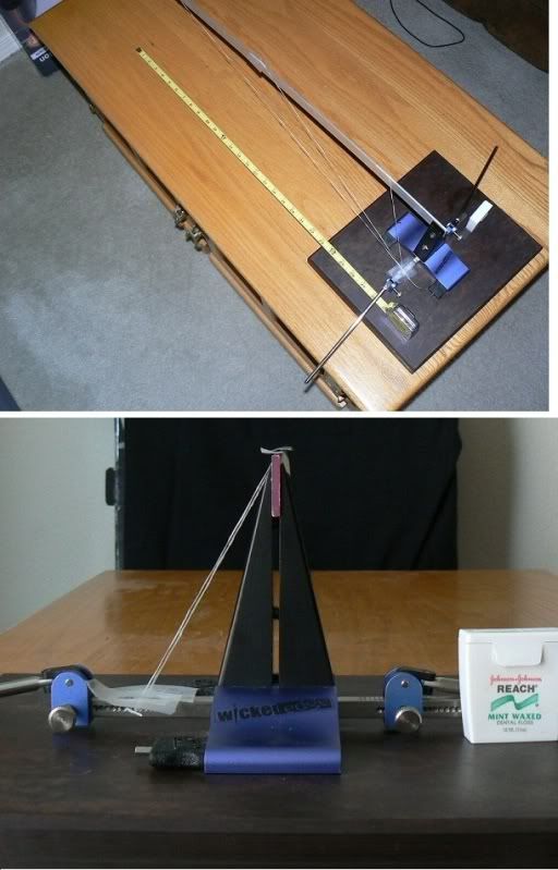
… so if you’re getting a change even with the blade horizontal, I’m not sure why. If I’m misinterpreting. let me know.
02/12/2016 at 9:12 am #31140Yes, you are misinterpreting my description. I’ll break it down to three simple points:
A. I sharpened the knife while it was clamped at a 20 degree angle.
B: I rotated the knife to a horizontal position, then measured the bevel at that point which had been directly over the vise.
C. I then moved the knife horizontally to place the heel directly over the vise and measured again.
This showed a difference in bevel angle at the heel versus the bevel at a point which had been directly over the clamp.
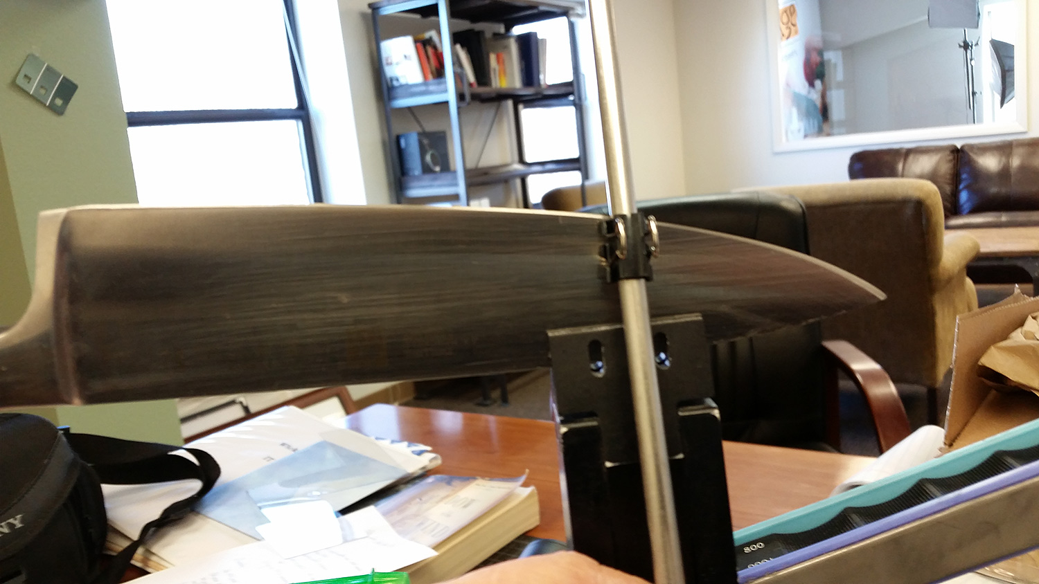
BTW, I have been trying to explain to others here that the angle doesn’t change along any horizontal line, no matter how far it is away from the clamp. My view of this was that if you consider the WEPS as it would be shown in a side view of an isometric drawing, you would see that the angle is constant, regardless of the rod position. Your bottom photo illustrates this view very well. Thank you for demonstrating this for me.
All are absolutely correct in stating that less than a half-degree of variability is nothing to be concerned about. But this whole discussion is about our basic understanding of the geometry of the WEPS. Clay says his setup resulted in zero difference and we ask why. My test showed 0.4 degrees variation over a span of only 61mm. From Clay’s photo, I’d estimate that his chef’s knife spanned three times as far, both horizontally and vertically. To not show a substantial variation is still a puzzlement.
02/12/2016 at 9:36 am #31141Yes, you are misinterpreting my description. I’ll break it down to three simple points: A. I sharpened the knife while it was clamped at a 20 degree angle. B: I rotated the knife to a horizontal position, then measured the bevel at that point which had been directly over the vise. C. I then moved the knife horizontally to place the heel directly over the vise and measured again. This showed a difference in bevel angle at the heel versus the bevel at a point which had been directly over the clamp. BTW, I have been trying to explain to others here that the angle doesn’t change along any horizontal line, no matter how far it is away from the clamp. My view of this was that if you consider the WEPS as it would be shown in a side view of an isometric drawing, you would see that the angle is constant, regardless of the rod position. Your bottom photo illustrates this view very well. Thank you for demonstrating this for me. All are absolutely correct in stating that less than a half-degree of variability is nothing to be concerned about. But this whole discussion is about our basic understanding of the geometry of the WEPS. Clay says his setup resulted in zero difference and we ask why. My test showed 0.4 degrees variation over a span of only 61mm. From Clay’s photo, I’d estimate that his chef’s knife spanned three times as far, both horizontally and vertically. To not show a substantial variation is still a puzzlement.
Ah, that makes more sense. To be honest though, there’s a lot of variables there… I’m not sure you could conclude that there was a .4 deg. variation. Multiple tests would have to be done… and my guess is, it would average out.
Did my earlier posts not help? My view is that the pivot doesn’t “see parallel”… it just sees an angle and sharpens at that angle. To be clear, there may be an angle difference between the two setups… for example if I had a blade horizontal and sharpened at 20 deg. and then pivoted the knife, I might now be sharpening at 18 deg. But, the angle along the blade won’t change… there’s really no height change in relation to the pivot. I think it’s confusing because viewing the knife… it looks like there is a height change in that the heel is higher than the part above the clamp. But tip the whole WE, and it will look just like the blade is “horizontal” again. I don’t think the pivot sees it any different… whether the blade is tipped or not… other than the initial angle. (Again, talking the straight portion here). That’s my theory anyway… if I missing something, let me know.
02/12/2016 at 11:12 am #31143Redheads,
Are you accounting for the rotation of the stone around the guide rod as the blade curves? People generally describe the motion of the guide rod as conical, which I think is correct, but within the path of the of the rod, the stone also rotates, changing the plane of contact with the blade. I notice this out toward the tip. If we were using square rods with square holes in the stone blocks, there wouldn’t be any rotation and the conical model would work.
-Clay
1 user thanked author for this post.
02/12/2016 at 11:34 am #31144Hmm, good point. When the stone traverses a curve, I think only a certain “part” of the stone width would be touching the knife curve. On convex curves (typical on chefs knives) the amount of stone touch would depend on the shape of the arc (or you could use one of the edges). The flatter curves (ie. straighter) would get maximum stone contact. On concave curves (weird knives) you could only touch the curve with the leading, trailing or both stone edges. I think this introduces another dimension which is pretty difficult to control and will introduce a variation in the sharpening angle. This could very well be an error source which overrides everything we are talking about here. Did you ever consider spinning cylindrical stones (LOL) ? It reminds me of Yan’s comments on the Gen 1 with 2 pivots slightly apart. I assume a complete analytical engineering error budget analysis was never done. I am an ME working for the DOD just as a reference.
BTW, in your experience what is your simplest/best test for sharpness (besides arm hair shaving). I use a fast chop into a bent piece of newspaper.
Your design is novel and remarkable. I can feel and hear the knife getting sharper.
ET and all, please chime in.
02/12/2016 at 12:11 pm #31145Hmm, good point. When the stone traverses a curve, I think only a certain “part” of the stone width would be touching the knife curve. On convex curves (typical on chefs knives) the amount of stone touch would depend on the shape of the arc (or you could use one of the edges). The flatter curves (ie. straighter) would get maximum stone contact. On concave curves (weird knives) you could only touch the curve with the leading, trailing or both stone edges. I think this introduces another dimension which is pretty difficult to control and will introduce a variation in the sharpening angle. This could very well be an error source which overrides everything we are talking about here. Did you ever consider spinning cylindrical stones (LOL) ? It reminds me of Yan’s comments on the Gen 1 with 2 pivots slightly apart. I assume a complete analytical engineering error budget analysis was never done. I am an ME working for the DOD just as a reference. BTW, in your experience what is your simplest/best test for sharpness (besides arm hair shaving). I use a fast chop into a bent piece of newspaper. Your design is novel and remarkable. I can feel and hear the knife getting sharper. ET and all, please chime in.
In studying the stone as it rotates at the tip, I’ve made a couple observations – it’s difficult to get a reading from the cube because, as you say, only part of the stone is touching the blade so it wants to rock. If you push with your thumb so that the trailing edge of the stone is contacting the blade, the cube reads a higher angle and if you press the leading edge of the stone into the blade, the cube reads a lower angle. What you say with concave curves is also true, only the sides of the stone contact the blade.
We do have some curved stones. I’ll play around with measuring the angles using those.
For testing sharpness, I usually start on my thumbnail to ensure the entire edge bites easily at a low angle. From there, I do a three finger test where I hold the knife in my dominant hand and then place the thumb of my non-dominant hand on the spine of the knife and the pads of three fingers lightly on the edge. I then slide them ever so slightly to feel the bite. Your brain will easily prevent you from cutting yourself if it detects the edge biting in.
-Clay
1 user thanked author for this post.
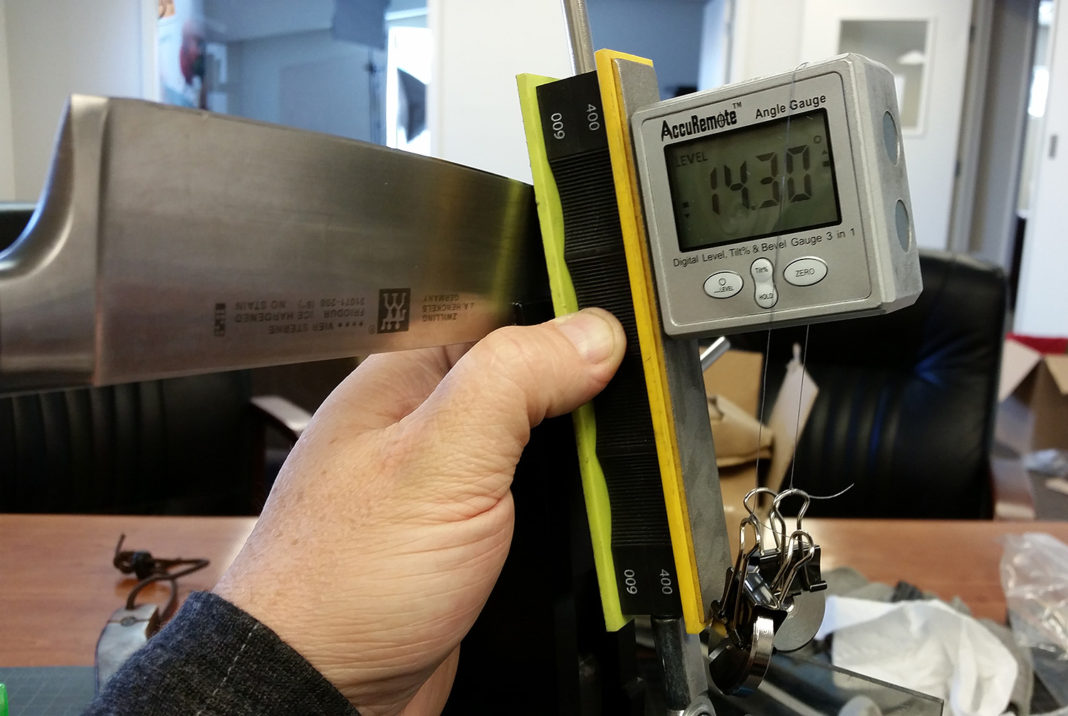
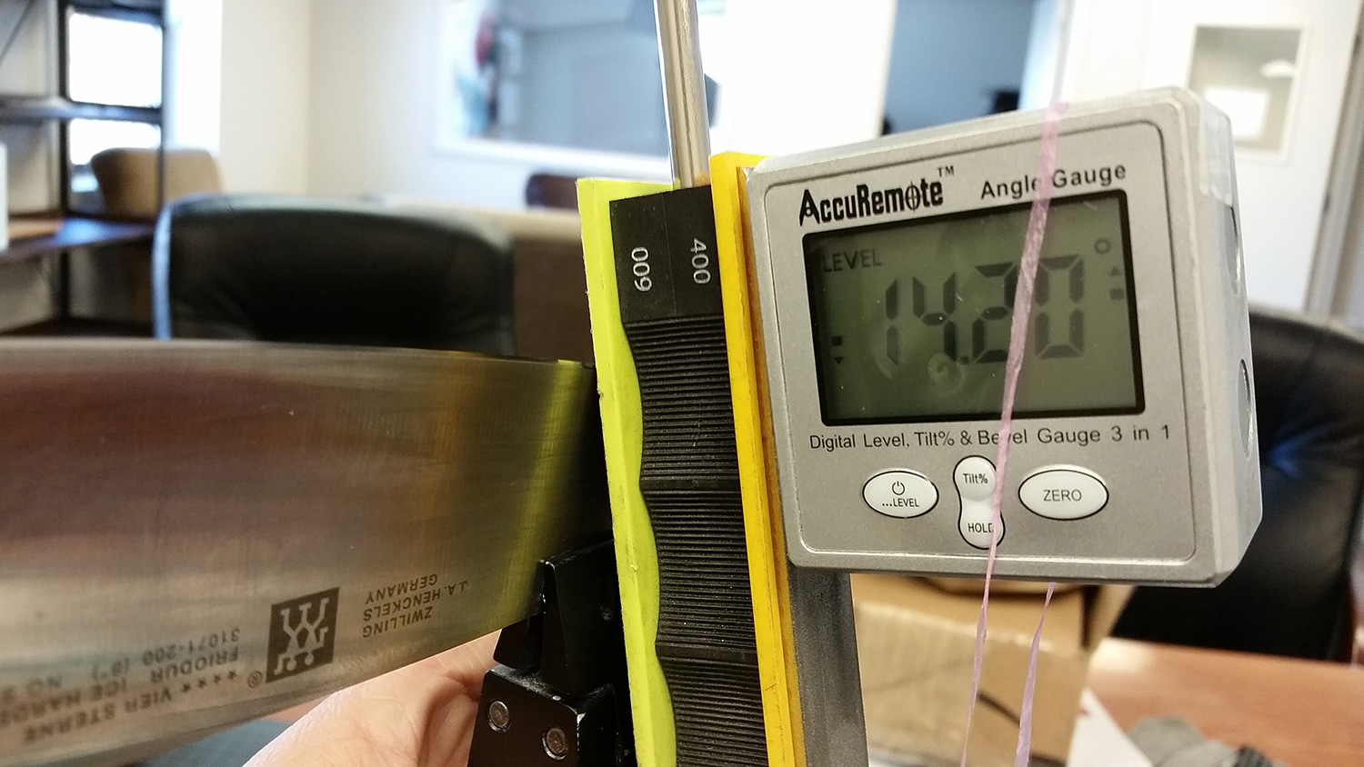
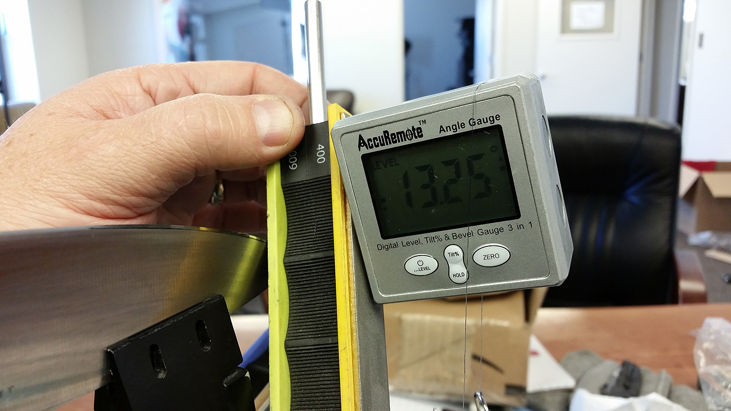
02/12/2016 at 12:27 pm #31146I’ve spent the morning studying the angle change along the length of the blade. I clearly have a lot more investigation to do… One thing that seems to have made our inquiry more complicated is that variances in user technique could render different results for the same knife setup. As an example, imagine two users taking turns sharpening the same knife, never removing the knife from the clamp or adjusting the angles. User A applies pressure to the stones with their thumbs so that the trailing edge of the stone is in contact with the blade and user B applies pressure with their finger tips so that the leading edge of the stone is in contact with the blade. User A should have more obtuse angles at the tip than use B. You can test this by coloring in the bevel with a marker and then applying pressure in different places while observing how the marker is removed. You can also do it with an angle cube. Getting the cube plumb is tricky, but you can use a square or you can put some strings with weights on your cube:
-Clay
Attachments:
You must be logged in to access attached files.
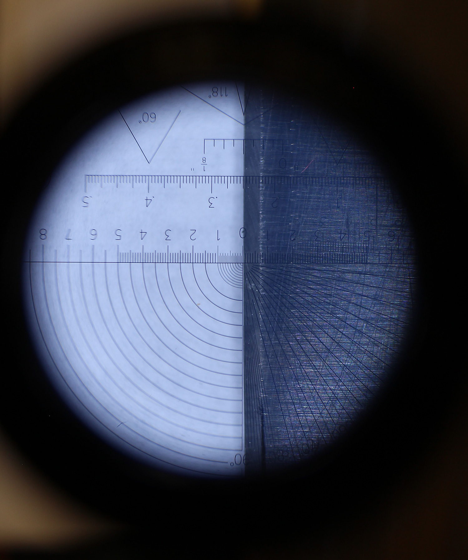
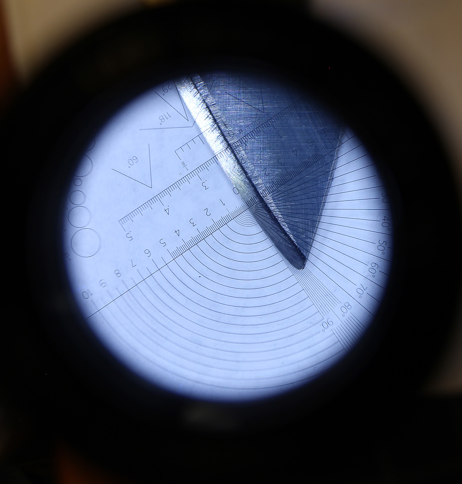
02/12/2016 at 12:47 pm #31150I’ve got a new loupe that I really like because it has a big objective lens and a very nice graticule. After fiddling a lot with the best positioning of the knife, I did some sharpening to establish a bevel and then took pics of the bevel width through the loupe:
You can see that the bevel width is about .7 mm along the straight section and just about .8 mm at the tip, so just slightly wider. There is marker still covering the earlier, wider bevel at the tip visible in the picture.
-Clay
Attachments:
You must be logged in to access attached files.
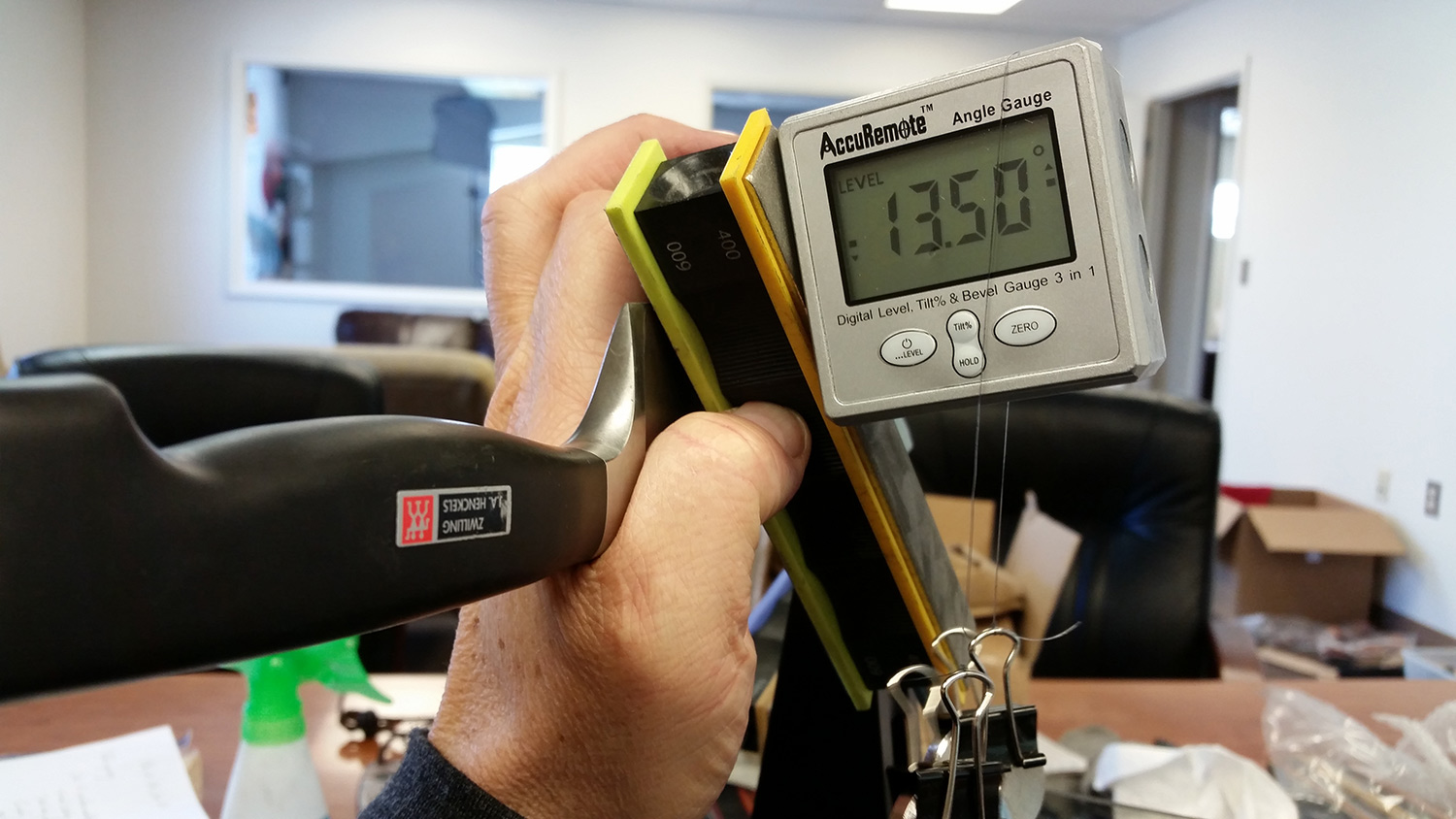
02/12/2016 at 12:55 pm #31153Here is the angle measured in three positions on the knife:
You can see that the angle at the tip and heel are very similar and there is an increase of angle in the middle position of the blade. Getting the tip measurement is really tricky because of the way the stone wants to rock on the bevel.
-Clay
Attachments:
You must be logged in to access attached files.
02/12/2016 at 1:01 pm #31157Do you mean 7mm and 8mm ? The 8mm almost looks like 8.5mm
Can you use a caliper to measure the thickness of the blade just above the top of the bevel at each point ?
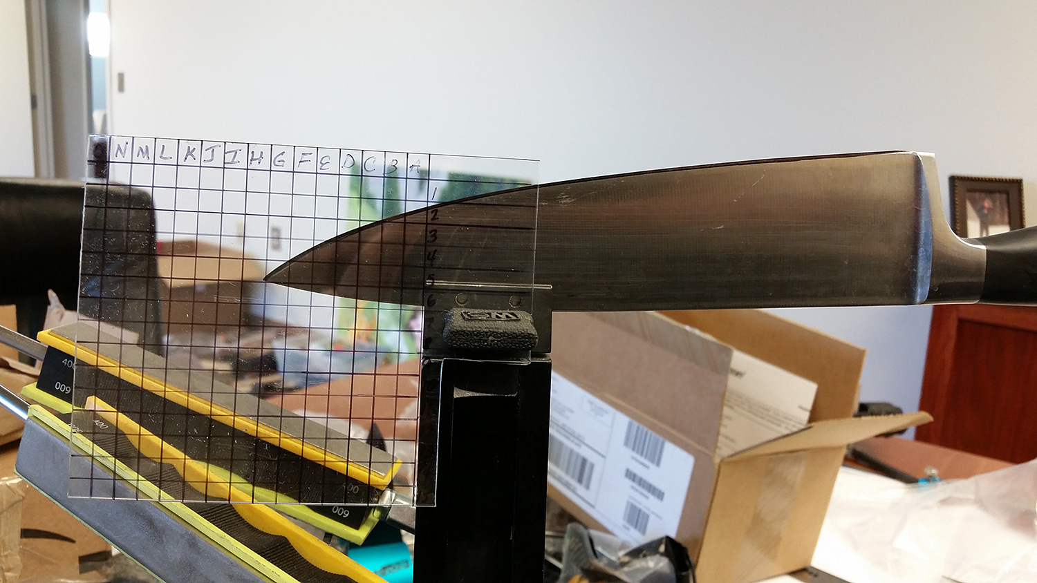
02/12/2016 at 1:02 pm #31159Here is the positioning I found to be most optimized (for the short amount of time I was tinkering with it):
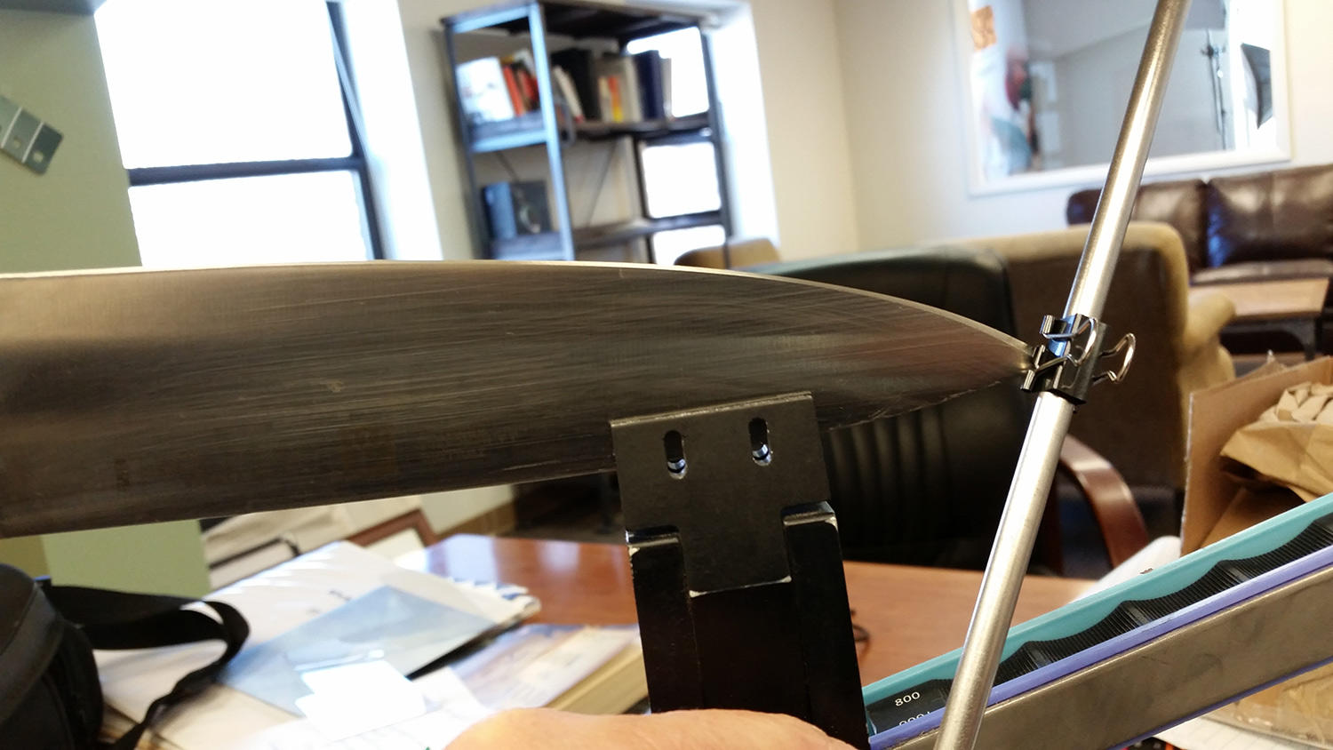
Using the binder clip in place of an o-ring, I checked to see if it would line up in each position. Unfortunately, it did not. It turns out that the tip of the knife would need to be much further forward for the binder clip to hit the edge in the middle and at the tip. I also found, like Curtis, that the clip could hit the edge at different points of the blade in a variety of knife positions. In each case though, there was a big range in measured angles. I’m not suggesting that my results are definitive, anything but, especially now that I’ve seen just how much the measurement can vary at the tip as different parts of the stone contact the blade. Next up I’ll repeat some of the tests while trying to control for stone rotation…
-Clay
Attachments:
You must be logged in to access attached files.
-
AuthorPosts
- You must be logged in to reply to this topic.
