Advanced alignment guide
Recent › Forums › Main Forum › Product Announcements › Advanced alignment guide
- This topic has 189 replies, 22 voices, and was last updated 05/24/2016 at 3:13 am by
 M1rrorEdge.
-
AuthorPosts
-
02/11/2016 at 12:02 am #31103
I’m afraid I don’t quite get it.
I agree for the straight section, however, in reality there is no straight section. There is only an “almost” straight section. Mathematically, a knife profile can be represented by a 4th order polynomial equation. Something like:

What’s x and what is y in the above equation?
The knife profile is actually a bunch of circle arcs combined together. Which one to pick in order to place the spherical joint at its center is my question.
I’m afraid I don’t quite understand this either. One could say the edge consists of an infinite number of points that are each located on a circle. Or do you mean something else?
You should be able to take a scaled picture of your knife, input your biased use factor, push a button and your phone tells you how to place your knife for the optimum edge.
Actually I’ve been thinking about doing this. But in practice it is more difficult than you might think. Knife profiles can have weird shapes. Even if you take an “idealized” knife consisting of a straight portion of the edge followed by a curved tip, there can be huge variations in the shape of the tip alone.
Molecule Polishing: my blog about sharpening with the Wicked Edge
02/11/2016 at 7:39 am #31107For a theoretical example… imagine you had a knife blade 1 mile long and you mounted it in your vise and your rods were 1 mile long. The angle at the end of that mile will be much much lower (while never reaching zero) than it would be directly above the vise.
Not if the edge is straight (unless I’m misunderstanding you)… the sharpening angle doesn’t change.
The main reason I run a double riser block in my setup is to allow for a larger radius and allow it to hit closer to the “primary” circle arc of any given larger knife. If its a small knife I can remove the riser blocks to reduce the radius from ball joint to knife apex to allow for a tighter sweep(narrower cone?).
Never really thought about this, but makes sense (which makes my head hurt). :/ Does add another factor to the equation…
I agree for the straight section, however, in reality there is no straight section. There is only an “almost” straight section. Mathematically, a knife profile can be represented by a 4th order polynomial equation. Something like: knife profile is actually a bunch of circle arcs combined together. Which one to pick in order to place the spherical joint at its center is my question. When Clay rotates the knife angle he is actually changing the location of the spherical joint relative to the circle arcs. We know there are different “best locations” depending if you want more or less acute angles at the tip as well as different total delta sharpening angles. You would think there are better ways to fine tune it than a sharpie. Yet of course it depends how anal you want to get about the edge. I am treating it as a mental engineering exercise in the quest for the perfect edge (whatever that is). You should be able to take a scaled picture of your knife, input your biased use factor, push a button and your phone tells you how to place your knife for the optimum edge. That being said I just did a 40 min touch up of my 4.5 inch Henckel steak knife at 17 DPS in a horizontal position with the spherical joint approximated to just outside the curve using my written log from last time (tip was at B on the steel ruler). The angle cube says I have a 4 deg total delta along the total edge (this was tricky and somewhat inaccurate though because the angle cube needs to be kept in the same vertical position as you traverse the edge – which I did by eye). Result: 400 grit thru strop green and I can read the newsprint, shave my arm and fast cut bent newspaper. I am sure it will cut my steak and hopefully my kids will keep their hands off it.
I guess I don’t get this either.
When you say “there is no straight section”… the obvious knives that come to mind… what about a wharncliffe? Tanto? Hawkbill? Would these fit into your formula? Your example seems limited to one style. I don’t understand the math, so this would help me understand a bit better (hopefully). 🙂
I do think it would be cool to “take a picture of a knife and get a setting”, but I’m not sure it would be that simple. Not only do you have to account for the shape of the edge, but also the width and length of the blade, thickness, taper (both spine to edge and heel to tip), not to mention fitting it to the factors and limitations of the sharpener. (In fact, I thought at one point Anthony and Clay were trying to do this… weren’t they scanning knives and plotting the profiles?)
I’m also curious about your “4 deg. change along the edge”. If you just mean an overall change from a point along the straight to a point at the tip I do understand, but if you’re saying it’s a gradual change along the entire length, I don’t (unless the entire blade was curved which it doesn’t appear to be). Nice sharpening job though.
Anyway, not saying your wrong… just trying to understand it.
I had a thought this morning that Clay is perhaps missing a golden opportunity at the shows where he and his crew sharpen hundreds of knives… he should have someone do nothing but document the knife and settings used. Would substantially increase the database for sure, and maybe a pattern would emerge.
(Now to see if this actually posts.) 🙂
02/11/2016 at 9:19 am #31114In fact, I thought at one point Anthony and Clay were trying to do this… weren’t they scanning knives and plotting the profiles?
True, we were working on it. I think Anthony has gotten really busy and I haven’t heard much from him recently. I’d still love to pursue it though I don’t have the math knowledge for it.I had a thought this morning that Clay is perhaps missing a golden opportunity at the shows where he and his crew sharpen hundreds of knives… he should have someone do nothing but document the knife and settings used. Would substantially increase the database for sure, and maybe a pattern would emerge. (Now to see if this actually posts.)
 It is a missed opportunity. We talked about it once. I’ll try to make sure we do it at Blade Show and any other shows this year. I’d love to get all those knives into our database anyway.
-Clay
02/11/2016 at 9:33 am #31116Y is the vertical distance from a horizontal reference line, X is the horizontal distance from a vertical reference line. It doesn’t really matter where the reference lines are exactly (they are constants). The equation represents how the profile changes (Y) as you move along the length of the knife (X).
You mentioned: “One could say the edge consists of an infinite number of points that are each located on a circle.” The infinite number of points are each located on an arc but the arc is not a circle. Some of the arc is a circle but others parts are an ellipse, etc. The important part of my thinking is that the spherical pivot will put a consistent sharpening angle on circles exactly centered around the spherical pivot (as well as absolutely straight knife profiles).
“Scaled picture” – If you take the second derivative (I think) of the equation you can determine mathematically how “fast” the slope changes. This would take into account the many types of curvatures near the tip. The math could then do an optimization to minimize the delta angle along the whole knife, suggest a best second or third position (not preferred due to need to blend your grinds) or maybe an angle adjustment for a certain part of the knife to compensate. I think the ultimate solution might entail some type of cam/electronics which could map the knife profile prior to sharpening and then force automatic “slight” adjustments as you are sharpening. Integrating the angle cube into the rod would also be interesting. I know I am overthinking it but the ultimate solution still interests me.
“4 deg. change along the edge” – I do mean an overall change. However, the vast majority of knives have no truly straight profiles (except maybe tantos, etc) and the amount of angle change is a function of the 4th order polynomial equation up until the time that any of the profile arcs fall onto the circle centered on the spherical pivot point. I think this is why the math and a computer can help (in lieu of sharpie trial and error). It is like using a computer model of your knife to optimize your sharpening on a guided rod sharpening system. Just part of my ultimate solution understanding. I wonder if we could use a 3-d printer in reverse.
02/11/2016 at 3:35 pm #31117Anonymous
Inactive- Topics: 14
- Replies: 427
I slide an ” O Ring ” on one of the arms, to set the knife for the sweet spot. Once set, I simply slide it down toward the bottom of the rod when done . If the rod had indications rings, I could use the ”O Ring ” to repeat the set up , noting which indicator ring on the rod was at the tip and which indicator ring was at the trailing edge of the radius. Once I used the O ring to set the sweet spot. If the rod was modified, it would always be present, and there would be no need for an external advanced guide card.

1 user thanked author for this post.
02/11/2016 at 4:33 pm #31118Simple elegance – I love it
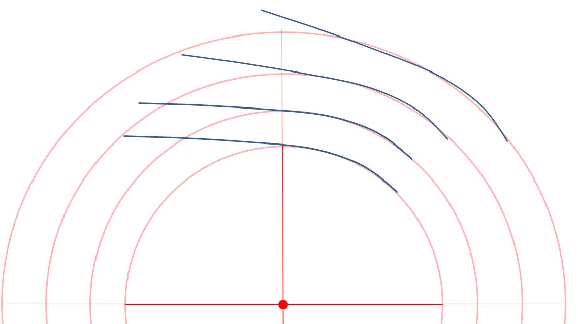
The following I think demonstrates what is going on with knife placement (either higher or angled) to the spherical pivot. The distance of the blue knife edge from the red circle shows the relative change of the sharpened angle from perfect. Perfect is defined as a red circle arc (or a perfect tangent from the end of the circle arc – ie. a straight line).
When Clay angled the knife he was optimizing the knife edge profile to the spherical point, that is how he got the perfect angles (within tolerances). NOW we have a way to visualize it live with ET’s O-rings. I can’t wait to get home and try it. BTW…you need a better name
What do you guys think ?
Attachments:
You must be logged in to access attached files.
1 user thanked author for this post.
02/11/2016 at 5:39 pm #31120We all know well that matching the belly of the blade to the arc of the stones will keep the bevels optimized. The question I think is confusing here is what happens where the heel of the blade deviates so much from the horizontal. Well, I couldn’t stand it anymore so I had to try it myself and got some interesting readings.
I found an old Chicago Cutlery butcher knife (about 10″) that looked like some kids had used in a sword fight and chucked it up in my Gen 3 vise. I flattened the edge to get it back to a reasonable straight line and reprofiled it at 20.0 DPS starting with 100 grit and going up to 1 micron diamond film. Constraints in the shape of the blade and the contact points in the vise put me at a 20 degree incline. The bevel at the heel was only 22mm higher (Y axis) than at the center of the vise and 61mm away horizontally (X axis). Then I measured:
First, I measured in the conventional way, attaching the AngleCube to the 1000 grit diamond stone as it was when I was finishing the re-grind. Being careful to align the ‘Cube with the same axis it had been zeroed on, I saw a difference of about 0.30 degrees (20.00 & 19.70) between the center of the vise and the heel.
Next, I used the Sharpie method. I switched to 9 micron film so I could see the scratch pattern on the background of the blackened 1 micron polish. Then, with the knife mounted horizontally, I made 1/4-turn incremental changes with the micro-adjust until the scratch pattern completely removed the Sharpie mark and eliminated the more highly polished areas. Then I took an angle reading with the ‘Cube held on the block. The point which was directly over the vise read 20.10 and the point at the heel read 19.70, for a difference of 0.40 degrees. Both points were effectively the same height over the vise.
Keep in mind that the difference in angle here was a function of only 61 mm horizontal and 22 mm vertical – less than an inch. Why was the angle measured at the forward point off by 0.10 degrees? I don’t think it’s entirely operator error. I’m confident that I can read my AngleCube to +/- 0.05 degrees. Perhaps the 20 degree slope contributed.
BTW, while sharpening, I noticed that the tip of my rod (really long at 14″) did move toward that side as I moved up the slope toward the heel. We assumed (well, I assumed) that the motion of the rod is conical, with the axis perpendicular to the knife, but here that’s not true. In addition to the changing diameter of the sweep, I think the axis of the cone is moving off-center as the stone climbs the slope. The result is a complex mish-mash of variables.
2 users thanked author for this post.
02/11/2016 at 6:27 pm #31121Your recap is a bit confusing can you post a picture of the knife
02/11/2016 at 7:10 pm #31122Inactive- Topics: 14
- Replies: 427
Simple elegance – I love it The following I think demonstrates what is going on with knife placement (either higher or angled) to the spherical pivot. The distance of the blue knife edge from the red circle shows the relative change of the sharpened angle from perfect. Perfect is defined as a red circle arc (or a perfect tangent from the end of the circle arc – ie. a straight line). When Clay angled the knife he was optimizing the knife edge profile to the spherical point, that is how he got the perfect angles (within tolerances). NOW we have a way to visualize it live with ET’s O-rings. I can’t wait to get home and try it. BTW…you need a better name What do you guys think ?
I’ve had this screen name since 1991…. Its a long story as to how I got this name.. Some day I will tell the story, here. I’ve told this story on many forums over the last 25 years.
The quick story, IM a retired GM design engineer ( Corvette studio ) in 1990 Lee Iacocca spent 1 billion dollar on the Chrysler engineering design center.
We at GM were using 3 year old Work stations. IN protest, I bought a Twin Turbo Dodge Stealth. When you work at GM, you Drive a GM product to work.
I drove to work in this Chrysler product, and instantly became a rebel. While its an unwritten law to support GM, and also take advantage of the employee ownership discount. I chose to be a rebel… When my Colleagues heard of my Twin turbo dodge stealth, they all came out to the parking lot. One of my colleagues called it my Evil Twin, and thus in 1991, I began to use that as my screen name.
02/11/2016 at 7:22 pm #31123Inactive- Topics: 14
- Replies: 427
I’ve always thought this sharpening stuff was way over thought. Mind you I am very new here, but with a fairly active mind. At 71, I may be retired but my mind isn’t. I hope I have not stepped on any toes, with my make it simple solutions.
ON another thought, you could make incremental detents in one of the rods as reference. Set the knife in the vice using my O ring, to set the sweet spot.
Once the knife is set, you could then put the rod to the tip of knife and note the detent number or color code. the move the rod to the trailing edge of the radius, and note the number on the rod or color. and you have two points of reference with the locating face in the vice jaws, at a specific height.
Just slide the rod to the first detent on the horizontal bar. Now you can use the rod as your measuring device. NO need for something extra… ONce the knife is set properly, you can then move your rod angles to the desired position
Again… I hope this is not an unforgivable curve ball to the advanced angle guide..
the under-cuts in the rod would not effect any action ( sweep )of the stone paddles. Just my thoughts in the think tank…. I apologize if I’ve stepped over the line.
Bill aka ET
1 user thanked author for this post.
02/11/2016 at 9:01 pm #31124Y is the vertical distance from a horizontal reference line, X is the horizontal distance from a vertical reference line. It doesn’t really matter where the reference lines are exactly (they are constants). The equation represents how the profile changes (Y) as you move along the length of the knife (X).
Readheads, if I interpret you correctly, your forumula describe the edge profile of a particular type of knife. That’s fine, but be aware that many knives have quite diferent edge profiles. For example, many of my kitchen gyuoto’s (which I’d regard as pretty standard) first have a long flat spot (and with flat I mean a straight flat spot), followed by some sort of curve. And the curve also differs per knife.
Molecule Polishing: my blog about sharpening with the Wicked Edge
02/11/2016 at 9:07 pm #31126The main reason I run a double riser block in my setup is to allow for a larger radius and allow it to hit closer to the “primary” circle arc of any given larger knife. If its a small knife I can remove the riser blocks to reduce the radius from ball joint to knife apex to allow for a tighter sweep(narrower cone?).
Never really thought about this, but makes sense (which makes my head hurt). :/ Does add another factor to the equation…
I think Cliff is right. The picture above by Redheads clearly shows it.
Molecule Polishing: my blog about sharpening with the Wicked Edge
1 user thanked author for this post.
02/11/2016 at 9:16 pm #31127As Yan mentions in note 2 at the bottom of page 57 “Mathematically, we say the knife edge is a differentiable curve” and if I remember from my many calculus classes you can then determine all kinds of things. We need a mathematician to help with an App to allow you to take a picture of a knife and determine the optimal set position and angle.
As I noted before, I think this is a very good idea. But there are some major challenges. First of all you need an algorithm that is able to translate a knife profile line drawing into a data structure that is easy to manipulate and that can be used for calculations.
But the main question is what you want to minimize. (1) Do you want the sharpening angle at the tip to be exactly the same as on the flat spot? That would mean there would be angle deviations along the curve at the end of the blade.
Or (2) do you want to minimize the angle change over the curve at the end of the blade? That would usually mean the angle at the tip is not the same as on the flat spot.
In other words: you have to determine what you want. There simply exists no optimal setup that satisfies all constraints (with the exception of a couple of knives with specific profiles).
I slide an ” O Ring ” on one of the arms, to set the knife for the sweet spot. Once set, I simply slide it down toward the bottom of the rod when done . If the rod had indications rings, I could use the ”O Ring ” to repeat the setup , noting which indicator ring on the rod was at the tip and which indicator ring was at the trailing edge of the radius. Once I used the O ring to set the sweet spot. If the rod was modified, it would always be present, and there would be no need for an external advanced guide card.
I think this is a very good idea, ET. Basically it means you have a very easy way to realize option 1.
The main reason I run a double riser block in my setup is to allow for a larger radius and allow it to hit closer to the “primary” circle arc of any given larger knife. If its a small knife I can remove the riser blocks to reduce the radius from ball joint to knife apex to allow for a tighter sweep(narrower cone?).
Never really thought about this, but makes sense (which makes my head hurt). :/ Does add another factor to the equation…
A very good idea again! Redheads pictures above show it.
But please keep in mind, again, that the optimal setup does not exist. It’s always a trade-off between angle changes over the curve and the maximum angle at some spot (usually the tip).
Molecule Polishing: my blog about sharpening with the Wicked Edge
1 user thanked author for this post.
02/11/2016 at 10:24 pm #31128Inactive- Topics: 14
- Replies: 427
Mark… This is knife sharpening ! Not coding algorithms for a smart bomb. I don’t mean to diminish the fine points ( pun ) of knife sharpening, But Homo Erectus sharpened stuff two million years ago.
Here are a few photos I shot with a small knife.. just to give you the idea… with the O ring I was able to set the knife in the most optimum position , in just a few seconds. There is only One right way to set a blade in the vice so that the sweep follows the edge. this O ring, gives you instant visual reference to the edge. Once the knife is set. all you have to do is set the angle using the cube.


2 users thanked author for this post.
02/11/2016 at 10:51 pm #31129Congratz Bill on finding a method that works to your level of satisfaction…the Josh Sweep(can I call it that?) is a great way to visually see where the angle is at on the blade.
I used to put the tape on a paddle with a horizontal line across to observe the sweep but these days I just pinch the rod with my fingers and live dangerous!

Thanks to Readheads for sharing the clear picture showing what a change in the radius arm length will do for adjusting the sweep to match a given blade size/shape. Well done!
Also greatly appreciate the work of Tom in checking angle variance. Less then half a degree should mean that under average conditions a detectable difference in the bevel width would be hard to notice?
Im still firmly in the camp for the usefulness of the adapter. In the world of a precision system where tolerances are being reduced to thousandths of an inch with custom bearings and rods, precision angle measuring devices and all slop and play is minimized in an attempt to gain micro-repeatability, where we are all on the edge of our seat for the latest SEM images(hint hint) studying the microconvexity of materials and how it effects and edge at sub micron levels it just seems natural to have a tool that could potentially allow us to remount in a repeatable manner beyond the +/- 2mm range.
Aloha, Cliff
2 users thanked author for this post.
-
AuthorPosts
- You must be logged in to reply to this topic.