Advanced alignment guide
Recent › Forums › Main Forum › Product Announcements › Advanced alignment guide
- This topic has 189 replies, 22 voices, and was last updated 05/24/2016 at 3:13 am by
 M1rrorEdge.
-
AuthorPosts
-
02/09/2016 at 3:35 pm #31053
Looking at the last mock up it seems starting at the number 9, the numbers sort of fade in with the vise. I really like where this is going, and have several knives that get brought in to me that this would be a big help. This has more than likely been hit on already, but making the pins for the guide key a little longer. Using the pro pack 2, some of the knives I sharpen just barely fit the vise. Will the current guide key still work with the new Advanced alignment guide? I am making the assumption that the new guide will be a little thicker than the current ruler. Thanks.
The markings were just done with a Sharpie but would likely be printed in white so they remain visible against the vise. I’ll have to look at making the pins for the depth key longer…
-Clay
02/10/2016 at 9:12 am #31060Clay, After reading the: https://knife.wickededgeusa.com/forums/topic/geometry-and-kinematics-of-guided-rod-sharpeners
Relative to your post: “The knife set up looks strange so I used the clamp to hold the knife after sharpening and took measurements w/ the laser goniometer. It’s registering a solid 13° along the whole blade. Weird, but true.”
How is that possible ? My understanding is that a consistent exact angle is only possible on the “uncurved “ part of the knife.
Except the special case of having a curve which is 100% fully on the arc of a circle (I think that is quite unlikely in reality)
Attachments:
You must be logged in to access attached files.
02/10/2016 at 11:20 am #31064I agree it’s weird and warrants further investigation. I took the knife home to test out the edge in the kitchen, but I’ll bring it back and see what I can learn. I definitely reground the bevels completely and lowered the angle from the factory substantially, so my results can’t be due to not having reached the edge and formed a new bevel. The part I found the strangest is that the heel measured the same. I was expecting it to be a much lower angle because it was elevated so much. Maybe Anthony Yan will come along and help us with the math. I wonder if the slope of the blade that is straight but sitting out of parallel to the tops of the clamp might have something to do with it. Maybe I’ll do some testing on another knife or a straight edge today.
-Clay
02/10/2016 at 11:34 am #31065Readheads’ comments rings true for me. How can you sharpen an edge mounted one inch or three inches above the vise and have the angle come out constant?? Does the angle of the blade somehow offset the error??
02/10/2016 at 11:40 am #31066Readheads’ comments rings true for me. How can you sharpen an edge mounted one inch or three inches above the vise and have the angle come out constant?? Does the angle of the blade somehow offset the error??
Exactly, how?!? I’m excited to explore it.
-Clay
02/10/2016 at 11:45 am #31069Does the laser goniometer process have a bias to it (like orthogonality, etc) ?
Does the angle cube verify the laser goniometer measurements ?
How about this (LOL): incorporate a mini cam structure in the micro adjustment cavity, before sharpening run the sharpening rod along the full edge of the blade to get a profile (captured by the mini cam), lock in the cam position and voila you get curve repeatability. You could also do it electronically with a piezo type of thing and incorporate the angle cube right into the electronics.
I am putting a visualization together from Yan’s Figure A4 movie and will post it shortly. Gotta love that Matlab – LOL
02/10/2016 at 12:15 pm #31072If you position the knife at an angle equal to the “prorated (for segment length)” average of all the tangential slopes then you <span style=”text-decoration: underline;”>may</span> be at such a position angle which would minimize the delta sharpening angle over the full length of the blade.
As Yan mentions in note 2 at the bottom of page 57 “Mathematically, we say the knife edge is a differentiable curve” and if I remember from my many calculus classes you can then determine all kinds of things. We need a mathematician to help with an App to allow you to take a picture of a knife and determine the optimal set position and angle.
1 user thanked author for this post.
02/10/2016 at 12:15 pm #31073The goniometer is pretty accurate (up to about 1 degree, I’d say), but the problem lies in interpreting its results. A tiny variation in the edge grind can cause almost unexplainable laser light spots on the goniometer circular thing (that’s how the goniometer shows its results). And interpreting measurements from convex bevels is a nightmare sometimes…
Anthony’s theory is spot-on and 100% accurate. The approach I took on my blog (link) and from which the above picture was taken by ReadHeads doesn’t take the various planes into account. Nevertheless it should still be a very good approximation of Anthony’s results and it also allows you to predict angle changes on edge curves.
If the knife was clamped as in the post of 02/03/2016 at 2:42 pm by Clay, there should also be angle changes on the straight part of the edge. If that isn’t the case, I’d blame the goniometer.
Molecule Polishing: my blog about sharpening with the Wicked Edge
1 user thanked author for this post.
02/10/2016 at 1:24 pm #31077The following attempts to correlate Mark76’s analysis to Anthony Yan’s. My conclusion is that for an 8 inch chef’s knife (15 DPS with a knife shape as shown in the Figures) the theoretical sharpening angle deviation over the entire length of the blade is a min of 0.7 deg and max of 5.2 deg. The min is at a spherical joint location at just before the start of the major curve (which ends at the tip of the knife) at x=-.11. The max is at a spherical joint location at the heel of the knife at x=-.4. Complete understanding can be obtained by reading Anthony Yan’s analysis at:
<span style=”color: #2f9bc1;”>https://knife.wickededgeusa.com/forums/topic/geometry-and-kinematics-of-guided-rod-sharpeners</span>Comments are desired: Collaboration is how Linux was developed and is improved. It is the backbone of the fastest supercomputers in the world.
Attachments:
You must be logged in to access attached files.
1 user thanked author for this post.
02/10/2016 at 2:17 pm #31084If the knife was clamped as in the post of 02/03/2016 at 2:42 pm by Clay, there should also be angle changes on the straight part of the edge. If that isn’t the case, I’d blame the goniometer.
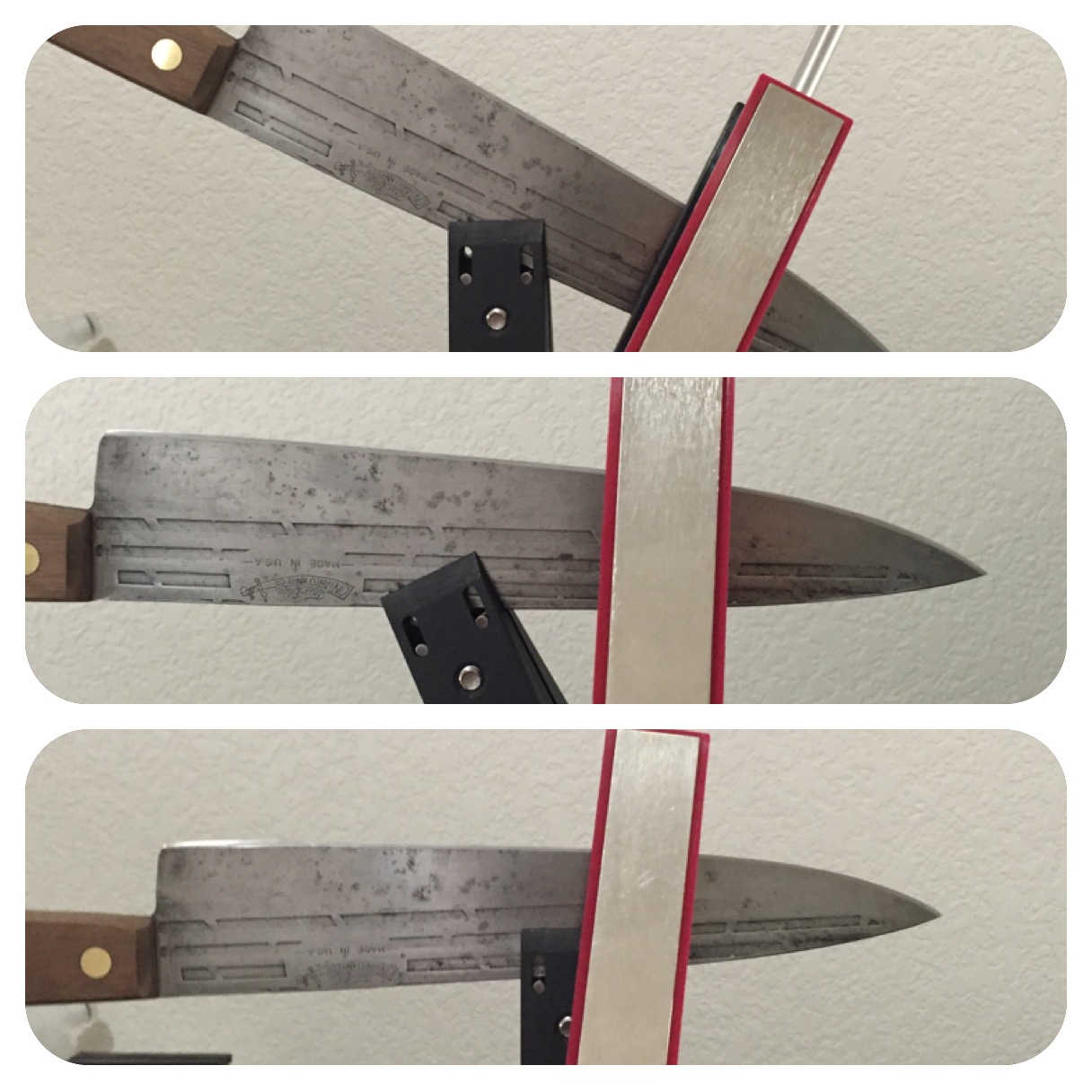
Nope, there won’t be an angle change along the straight portion, even if the knife is clamped at an angle. If you think about it, the pivot doesn’t “see parallel”… it just sees a straight line.
If you need a visual, clamp a blade at an angle, then tip your whole WE until the blade is parallel (to the ground)… to the pivot it “looks” the same as if you mounted it parallel to begin with.
Edit: Here’s a picture…
If you clamp a blade at an angle (top photo), then rotate the WE so the blade is parallel to the table/ground (middle photo), it looks no different to the pivot then the blade mounted parallel to begin with (bottom photo).
Attachments:
You must be logged in to access attached files.
3 users thanked author for this post.
02/10/2016 at 2:51 pm #31087If the knife was clamped as in the post of 02/03/2016 at 2:42 pm by Clay, there should also be angle changes on the straight part of the edge. If that isn’t the case, I’d blame the goniometer.
Nope, there won’t be an angle change along the straight portion, even if the knife is clamped at an angle. If you think about it, the pivot doesn’t “see parallel”… it just sees a straight line. If you need a visual, clamp a blade at an angle, then tip your whole WE until the blade is parallel (to the ground)… to the pivot it “looks” the same as if you mounted it parallel to begin with.
You’re right. That’s exactly due to the fact that I didn’t take the planes into account.
Molecule Polishing: my blog about sharpening with the Wicked Edge
02/10/2016 at 3:52 pm #31089I probably could have made it easier and just did this…

Attachments:
You must be logged in to access attached files.
1 user thanked author for this post.
02/10/2016 at 6:45 pm #31092I agree for the straight section, however, in reality there is no straight section. There is only an “almost” straight section. Mathematically, a knife profile can be represented by a 4th order polynomial equation. Something like:
The knife profile is actually a bunch of circle arcs combined together. Which one to pick in order to place the spherical joint at its center is my question. When Clay rotates the knife angle he is actually changing the location of the spherical joint relative to the circle arcs. We know there are different “best locations” depending if you want more or less acute angles at the tip as well as different total delta sharpening angles. You would think there are better ways to fine tune it than a sharpie. Yet of course it depends how anal you want to get about the edge. I am treating it as a mental engineering exercise in the quest for the perfect edge (whatever that is).
You should be able to take a scaled picture of your knife, input your biased use factor, push a button and your phone tells you how to place your knife for the optimum edge.
That being said I just did a 40 min touch up of my 4.5 inch Henckel steak knife at 17 DPS in a horizontal position with the spherical joint approximated to just outside the curve using my written log from last time (tip was at B on the steel ruler). The angle cube says I have a 4 deg total delta along the total edge (this was tricky and somewhat inaccurate though because the angle cube needs to be kept in the same vertical position as you traverse the edge – which I did by eye). Result: 400 grit thru strop green and I can read the newsprint, shave my arm and fast cut bent newspaper. I am sure it will cut my steak and hopefully my kids will keep their hands off it.
Attachments:
You must be logged in to access attached files.
2 users thanked author for this post.
02/10/2016 at 9:49 pm #31099The knife profile is actually a bunch of circle arcs combined together.
Great job on the knife and thanks for your work filtering down higher math into practical usability.
The main reason I run a double riser block in my setup is to allow for a larger radius and allow it to hit closer to the “primary” circle arc of any given larger knife. If its a small knife I can remove the riser blocks to reduce the radius from ball joint to knife apex to allow for a tighter sweep(narrower cone?).
Great stuff!

1 user thanked author for this post.
02/10/2016 at 10:35 pm #31102I’m not as smart as many others on here, but the way I understand it in my simple brain is: ” Any point that remains the same distance from the pivot of the rod base will remain at the same angle, whereas any point further from the pivot will lower the edge angle and any point closer to the pivot point will increase the edge angle.”
A simple way to think about it is this… The Wicked Edge vise and degree bar are only good when the edge is set at 5/8″ above the top of the vise (at least, that’s what it used to be) and when measuring the angle right above the vise at that point. If you put a wide kitchen knife or even cleaver in there and it elevates the edge 3″ above the top of the vise then the angle will obviously change to a lower degree. The same principle applies any time the edge gets farther from the rod pivot. For a theoretical example… imagine you had a knife blade 1 mile long and you mounted it in your vise and your rods were 1 mile long. The angle at the end of that mile will be much much lower (while never reaching zero) than it would be directly above the vise.
This is why tilting a knife comes in handy… when you can’t mount a knife all the way back in the vise to where you are clamping all the way at the front of the blade (due to geometry or other limitations) you can simply tilt a knife and the angle will become more obtuse at the tip.
I may be wrong but this is how I see it!
-
AuthorPosts
- You must be logged in to reply to this topic.


