Blade alignment in the clamp: sweet spot & constant bevel angle/width

Clay, yes, the circles on your revised pdf line up (the cutout lines for the vise are too narrow, but that’s just a matter of cutting it bigger).

I think no matter where the pivot is located along the angle bar, it’s always bisecting the center of the vise, and it’s still tracing out circles in the plane of the blade’s edge no matter the location of the pivot on the angle bar. The radius that corresponds to the edge of the knife at the clamp centerline will vary depending on the angle bar setting, but since the circles are just an alignment reference and their specific location/radius doesn’t matter, my thinking is that this jig serves the same purpose regardless of the actual angle bar setting.

But I always reserve the right to get smarter and change my thinking ;o)

@graphite - I’m thinking of trying the following to continue testing your ideas:

  1. Set the guide rod at some angle
    1. maybe start at 20 degrees just to have some place to start
  2. Attach a blank piece of paper to the vise, on the opposite side from the guide rod that I'm testing
  3. Attach a pen to the guide rod such that it can scribe on the paper and is aligned with the top of the vise
  4. Complete that semicircle
  5. Move the pen up the guide rod 1/2" and reattach, then scribe a new semicircle
  6. Repeat for a few iterations

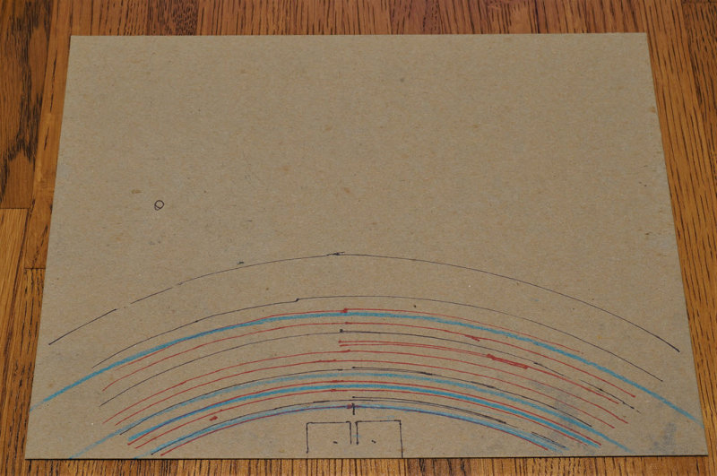
Clay, I did something similar to that before I built the jig. I traced out semi-circles as I held a sharpie in a constant position on the guide rod, and then at various offset, parallel semicircles when I moved the position of the sharpie on the rod. I used a piece of thin cardboard since the fixed length of the guide rods gets in the way if you use something too stiff like box cardboard. But it all makes sense when you think about the rod on a fixed pivot point and the tip of the sharpie at a fixed point on the rod. With those constraints, all it can do is trace out a circle on the plane that bisects the center of the blade edge. Still, it’s useful to see it with your own eyes.

Here’s a photo of that original cardboard test I did, including the outline of the vise jaws. You’ll have to forgive the jittery sharpie lines, since this setup with the cardboard and manually holding the sharpie on the rod was a bit flimsy.

Ignore the blue lines. After I completed this exercise I took the cardboard and taped it down on a workbench, and then I got out my beam compass and put the blue colored pencil in it. I wanted to convince myself that these arcs I drew by sweeping the sharpener rod with the sharpie were in fact part of concentric circles. The beam compass traces in blue (with the pivot point perpendicular to the centerline of the jaw outline) confirmed it for me.

Let me know if you get a similar result with your tests.

@graphite I’m trying to post photos of my results of the little test I made with the 7" diameter circles and the angle set to 20 dps but so far not having much luck.


Hi Clay, you must have been testing something different from what I was thinking. What are we looking at here, and more importantly, what conclusion did you reach?

I was just checking out how the marks on the guide rod lined up with the semicircles with a starting diameter of 7". It doesn’t show well in the photos because the paper I was using was flopping around but the marks on the rods lined up pretty well throughout the rotation. I don’t really know what that means yet other than it looks like there are some fun avenues for exploration with the concept. I’ll try to build a sturdier model to test after the Christmas break and see what comes up. Then I guess I’d try it out on some knives to see what it does to bevel widths.

Clay, how come you used 7" diameter (rather than 7" radius)?

I think because the vertical distance from the pivot to the top of the vise is 3.5".

[quote quote=44093]

Clay, how come you used 7″ diameter (rather than 7″ radius)?
I think because the vertical distance from the pivot to the top of the vise is 3.5″.[/quote]

I see the logic in that, but my vise measures about 5.75" vertical from the pivot point on the angle bar to the top of the vise jaws. But either way, I’m scratching my head wondering why the circles I traced out with the guide rod+sharpie on my first cardboard experiment and then transferred that to the workbench where I used the beam compass which matched up at a 7" radius for the smallest circle (which doesn’t match to either 3.5 or 5.75" radius). There must be some 3-dimensional geometry issue at play that I’m not seeing at the moment.

Does it have anything to do with the pivot point is out to the side away from the plane of the arc board. You’re not drawing a flat circle or arc like you did with the beam compass, working down flat where your pivot point was at the center and on the same flat plane. You’re leaning into the cardboard at an angle before you touch it to draw your arcs.

Great stuff Graphite, are you an engineer ? A few of my thoughts:

  1. You should read Anthony Yan’s work (link below) on this, you are doing the physical verification of his mathematical proofs. Watch the video (second link below) below for optimum placement on a specifically shaped chef knife, it is really cool. The movie simulation works only for that specific shape. Someone should write an app which would take a picture of a knife, do the math and tell/show you the optimum position.

  2. Putting a rubber washer on the pivot rod (just the right inside dimension to allow you to slide it up and back down to the bottom, out of way, yet hold a position if you want) will allow for a radius reference while you tweak the position of the knife in the clamp.

  3. I think you could just scribe the radius(es) into the current advanced alignment guide to show “optimum positions”.

  4. Out of the box thinking – if you went back to the “pre-spherical bearing” days you might be able to integrate an adjustable cam to tweak the angle as you traversed the entire edge. This would yield an additional degree of freedom to approach perfect angles.

  5. It would be pretty cool to integrate a dual axis inclinometer into the rod which would beep as you traversed the entire edge to give you optimum angle feedback.

  6. A dual axis inclinometer (the current one is single axis and must be plumbed), would give you the angle data you need as you traverse to the entire length of the blade. Visual bevel “heights” are also a function of the blade thickness. If you want the same bevel height and bevel angle along the entire knife edge then the blade must be equally thick along the entire length (doesn’t happen), it’s a balance like everything.

https://drive.google.com/open?id=0B5t7FJ9Zmj1hR29IeWQteHRXams

https://drive.google.com/open?id=1qFEZRtyAcy20C1AFatt5XlmAeuYed-ag


If the drawing is held vertical from the vise, some of the error would be geometric because the arcs on the drawing are not in the same plane as those on the rod. The rod only scribes a true radius on the cone of its rotation, so if you’d remove everything above the radius you’re checking, you’d see the mark on the rod following its matching arc.

Or am I FOS, as usual?

Isn’t this exactly what Tom was saying? You could easily try it out by using a pencil attached to a rod, so that the rod is complete vertical.

Great subject, by the way, guys! The only thing I have to be wary of is not to make things too difficult for beginners to comprehend, so that the WEPS gets the impression of being a bit difficult in use (which it is not - but because we put so much emphasis on advanced things it might get).

[quote quote=44102]

The only thing I have to be wary of is not to make things too difficult for beginners to comprehend, so that the WEPS gets the impression of being a bit difficult in use (which it is not – but because we put so much emphasis on advanced things it might get).[/quote]

I am whole hearted behind this statement. Ever since all this need for in depth analysis and understanding the theory of exactly how it works is portraying and stimulating a lot of discussion and conversation far more complicated than it really is. Any one who just dropped in to the middle of this looking to learn what the WEPS are all about could likely be scared off by the detail!

Many if not most users have simply clamped knives with a “sharpie” marker, to find the “sweet spot”, and have gone on to become very capable experienced sharpeners producing show stopping results. With little more then the instruction book it came with, with the help of the Forum and time and practice I am one of these individuals. The yearning for knowledge is important and certainly there is a place but lets not forget we don’t need to understand the mechanical theory, three dimensional trigonometry, dual axis geometry and motion dynamics to use a WEPS to sharpen a knife.

Keep in mind that the original objective was/is to see if it’s possible to develop a knife alignment jig FOR THE VERY REASON of simplifying the knife positioning down to an easy-to-follow and repeatable process (for beginners and experienced users alike). It’s to eliminate the guesswork and trial-and-error.

It’s looking like there is some family of curves drawn on this jig that will achieve that end, and the main unresolved question is, where should the center point of the circles be, relative to the top of the jaws? That’s important because it changes the slope of the arcs that are drawn.

Once we know the location of that center point, you can draw the “parallel” circles on the jig at any spacing, because they are just a guide for aligning the curved part of the knife.

But it’s also important to know how to handle the straight (or “straight enough”) part of the knife, and treating many knives as having 2 segments (a relatively straight segment and a curved segment) can greatly simplify the process for new users. This was an unexpected (for me anyway) observation that I wouldn’t have made if I had not undertaken this jig-building process.

MarcH’s observation that experienced users have been getting great results with the WE without this jig I think just speaks to there being a fairly wide range outside of the theoretical ideal where you get good results. And that makes a jig even easier to apply.

But (and this is important) the jig should be based on the correct theory (i.e. the correct center point). Once that is established, people can use the jig without needing to read the theory behind it.

I also think there’s merit to Redhead’s suggestion of putting a rubber washer on the rod and sliding it across the blade edge while moving the washer and varying the knife position. And this sounds similar to what Mark76 does already. But I think this circle contour jig is fundamentally safer (it’s static, with no sliding things across the blade edge), and potentially quicker (you just tilt/move the knife until it matches a curve on the jig), so I do think it’s worth seeing this through to a solution. If such a thing were available when I was shopping for sharpeners a month ago, it would have been bonus points for the WE sharpener.

I completely agree, Graphite, I just wanted to make people aware who only read this forum scarcely (and there are quite a few of them) and then think “this must be complicated”. But you’re completely right it is not and it makes live easier.

I admit that, upon first reading of this thread, my eyes glazed over and I saw little applicability for my own limited sharpening experience with WE. I’ve gotten to the point where I can get a very sharp edge on my kitchen knives and that was my goal when I bought my WEPS. But then I see other threads as well as this one that could be very useful to me in the future. My current state of knives that are happily “much better than before” will over time become “not quite good enough” and that’s when I’ll re-read and possibly apply these more esoteric subjects to my own practices.

I understand how these topics COULD turn off potential buyers by implying a necessary and undesired level of complexity. However, I believe most of us novices would view this thread as a process tweak to get to another level of expertise and better results as opposed to a requirement for even basic sharpening. On the other hand, topics like this one demonstrate how advanced and innovative thinking can improve the process and maybe the overall system design…good things I think.

It would be fine with me if moderators want to move this thread into “Techniques and Sharpening Strategies” >> “Advanced Techniques and Sharpening Strategies” sub-forum. Maybe that would eliminate the angst some of you guys feel about it.

I just put it in the “Basic Techniques” sub-forum because I’m still a novice with the WE, and because the potential end result of using the jig could be considered a basic technique that helps new users. But granted, the intermediate theory steps in arriving at that end result–which is what most of the content of this thread has been concerned with–is not something uninterested new users need to read.

This is the new home of the thread started by forum member and contributor Graphite - “Blade alignment in the clamp: sweet spot & constant bevel angle/width” It’s been agreed the level of discussion and theory involved is above a basic beginner’s level and possibly confusing. The discussion is very worthwhile and should be continued as a very valuable tool and understanding of clamping method is being developed. By no means is the understanding of this theory or discussion needed or necessary to use and operate any WEPS to it’s best potential.

We invite any and all contributions to this thread. It was moved to, I believe, a more appropriate Forum Category to avoid confusing, new, inexperienced users, with the more advanced treatment of knife clamping discussion.

I read the relevant parts of Anthony Yan’s paper that Redheads referenced above in post #44099 (the first link). It’s quite an impressive body of work, and it’s too bad that Anthony is no longer posting.

In Anthony’s paper on pg 53 he summarizes the straight blade case (using a tanto blade with a straight main blade and a straight but angled tip portion) for all WE devices that use a spherical pivot joint (I believe this means GEN2 and beyond), “we conclude this chapter by noting that the current WEPS-GEN2 uses a spherical joint (spherical rod end) in its design, and can grind perfect dihedral angles both along the main edge and the tip edge of the tanto knife.”

The spherical ball joint is an important condition on that outcome. Without that condition (e.g. the GEN-1 WE doesn’t have a spherical ball joint) it’s not the case that straight and slanted blades will be ground at perfect dihedral angles regardless of left or right shift of the sharpening rods. I don’t recall that requirement listed in the discussions about straight blades and grinding perfect bevels, so I thought I’d note it here.

For the curved blade case, the theory says that the center point of the circle (shown in figure 6.8 on pg 65) is the (perpendicular) projection of the spherical ball pivot point (denoted as p in that figure) onto the plane defined by bisecting the blade along its centerline lengthwise (denoted as point q in that figure). This is equivalent to the plane that bisects the clamp down its centerline from a side view.

Now that we know the theoretical underpinning for the center point of the circle, we have to define some fixed reference on the vise for the purpose of drawing the smallest radius circle onto the circle contour jig and being able to mount the jig onto the vise relative to that reference, in a repeatable manner.

I’m going to use the line across the top of the vise jaws as that reference, but adding a quarter inch above that so that (once we cut out the vise outline from the jig) the circle is still visible. Without adding that quarter inch to the reference, the top of the smallest circle would be cut away along with cutting out the vise cutout.

With that in mind, here’s a graphic showing the measurements on my F&S Pro vise, which results in a radius for the smallest circle (relative to a point 1/4 inch above the top of the jaws) of 6.13”. When making the circle contour jig, the vise cutout (in particular the part that rests on the top of the jaws) should be cut 1/4 inch below the high point of the smallest circle in order for the reference to translate back to the correct circle centerpoint position.

I assume the explanation for the 7” radius I originally thought was correct is simply that the cardboard cutout was flimsy and bent out of the plane of the knife when I was drawing the circles. But regardless of the reason, that wasn’t the correct radius and the resulting circular arcs would have been off.

I’d be interested if others could confirm my measurements on your vise. I’m not positive but I think some of the earlier vises might have different measurements for the centerpoint of the pivot joint relative to (a quarter inch above) the top of the jaws.

PS, the photo also includes my newly-minted platform to mount my F&S vise. It’s just 2 pieces of 3/4" baltic birch plywood glued together (1.5" thick) and I added a couple t-tracks for TBD future use.