Tom_G
Forum Replies Created
-
AuthorPosts
-
07/23/2022 at 2:17 pm #58051
My method is a form of “finding the sweet spot” except that I don’t try to match any existing bevel – which is what the sweet spot is originally intended for. I pick a mounting position which matches the sweep of the stone to the belly of the knife. Another way of looking at it is to imagine a line forming the radius of the edge’s belly and position the knife so that the line passes through the pivot point of the rod bearing. Then adjust the angle with the stone positioned at the tangent point where the belly meets the straight part of the edge. The position you find need not have the blade’s spine flat on the key pins. No matter what the angle of the blade, relative to horizontal, the bevel angle will be constant throughout the length of that straight section, even if it extends well away from the vise. This is a key factoid that we use to give us flexibility in positioning blades in our vise. Yes, the deeper the belly, the more variability in angle you’ll see along that belly, but for most knives, it’s simply not a problem to wring our hands over. Upshot: Position the belly to match the sweep of the stone and trust that the straight section will follow uniformly. No belly? Whoohoo!
Ahh, so your method seems pretty quick as a way to get a near optimally uniform sharpening angle, since, as you point out that angle is uniform if the edge of the knife traces out part of a circle about the pivot point -and- that the sharpening angle is uniform along a flat edge even if its tilted. I came across a discussion, in my explorations of the forum before I dove in and purchased the sharpener, that described a template for locating where the belly should be https://knife.wickededgeusa.com/forums/topic/blade-alignment-in-the-clamp-sweet-spot-constant-bevel-angle-width/
Your approach, I think, matches what you would get using graphite’s template, but — if I understand you correctly, is quick because you just use a point on the pivot arm to make the belly match the circle the point sweeps out. Wow.
The part of this that I was never able to locate information on was how far off the sharpening angle would be if a blade was not a straight section connected to a belly that could map onto a circle. I think your approach may be optimal as well for such blades, but my curiosity got the better of me, so I am calculating away….
Thanks — Tom
07/23/2022 at 1:51 pm #58050Looks like you are trying to find the sweet spot.. where to clamp the knife so the angle changes the least.. It is sometimes more work than needed .. if the knife is not relatively straight, I just do it in sections an change the where and how it is mounted to make the section level.. This type of math exercise is neat, but really not helpful when it comes to making your knife sharp to cut whatever it is you desire it to cut.. Have fun!
Got it — thanks and understood. I am just a newbie with a computational/design bent for whom you have correctly identified a big part of my justification for doing this — its fun!
07/23/2022 at 1:47 pm #58049I have this from several years ago. It’s a chart or graph from a spread sheet that was put together by an engineer who is a Wicked Edge user. Is this what you’re talking about? It’ll let you set the bevel angle by edge height and ball end distance from the knife’s centerline. This is to determine a single set angle for the whole knife. The guy that made the chart did all the computations for it. Probably using a mathematical equation similar to Tom_G’s. offset-of-ball-vs-angle
Marc,
Thanks for digging up the info! The features of that curve is part of the calculation above. I am pretty sure the graph is of the formula Offset = Height * atan(a fixed angle) + (1/2 of the width of the diamond block). It incorporates the width of the block as part of the analysis to gives you how far off the center the ball should be to get a particular sharpening angle for a given blade height. It assumes, though, that the blade is flat and horizontal at the height point, which can generate corrections. Pretty glad to see that this piece of things makes sense — Thanks!!
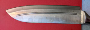
07/21/2022 at 12:09 am #58042So I have some preliminary results. These are for the following (inexpensive) knife.
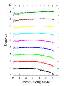
I have calculated the real sharpening angle for the various positions across that blade for a number of different mounting spots. The mounting spots are 2″, 2.25″ 2.5″ ….. up to 4″ from the blade start (right side of the image). The sharpening angle is adjusted to be 18 degrees at the mount location and the blade is pushed down so the both mounting pins are in contact. The variation in the sharpening angle across the blade is shown as calculated for each mount position in the figure below. for readability, the 2″ mount has 16 degrees subtracted from the calculated angles (so its on the bottom and is black). The 2.25″ mount position has 14 degrees subtracted so its just above the 2″ data set (it is red and its target angle looks like its 4 degreees). The data is a bit noisy, which is from the conversion of the picture to top and bottom of blade XY positions. (this can be improved).
This is just my first computation, so I expect accuracy and noise to improve. Hopefully this makes more clear what I was after….
Tom
-
This reply was modified 2 years, 8 months ago by
Tom_G.
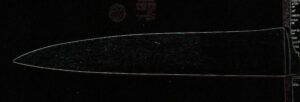
07/20/2022 at 4:29 pm #58037Nope its just a trial posting. The image is of a cell phone picture of a knife that has been subjected to an edge finding program as a first step toward converting it into x,y numbers for analysis. Those letters you see are whats printed on the red folder I used as a background, The edge find does pretty well with those.
Thanks again for the help — Tom
07/20/2022 at 12:13 pm #58034Success — but I have to add it as an attachment, then post, then insert as media in a new post, then delete original post with the attachment.
Not sure this is how its supposed to work, but thanks for the help!!!
-
This reply was modified 2 years, 8 months ago by
Tom_G.
07/19/2022 at 4:16 pm #58006Marc H,
Thanks for answering. But the issue is that I am never offered that second step. (i.e. click it so it’s marked with a check mark in the square”) I can try to add my image to the image gallery, but it fails and tells me: “Sorry, you are not allowed to attach files to this post.” Since it never makes it tot he gallery, I cannot insert it in the post.
I can see in the gallery that -you- put in the gallery, and can add that, but my own image do not upload.
Tom
07/16/2022 at 5:00 pm #57991airscapes — thanks for touching base, and for the info and guidance about sharpening angles. I am thinking that I did not introduce that first post very well. Rather than determining an angle to use for a blade, the calculation is aimed at finding the variation of the sharpening angle for each portion of the blade. My understanding is that setting the knives mounting position is key in getting the sharpening angle uniform across the blade. The recommended approach, if I understand things correctly, is to use a sharpie marker and a fine grit to see what the sharpening angle had been, and then to see how uniform the angle is across the blade. And then repeat at another mounting place to try to make improvements in that uniformity if need be. My discussion above is essentially a beginning of a computational substitute for the variation part of that process — knowing the knife geometry (just from a picture) its possible to get the variation in the sharpening angle across the blade. If put in a spreadsheet, you can get numbers for the angle at positions along the blade, and then change mount values and calculate again. Not sure it’ll be easier than the sharpie approach to mounting, but it will accurately yield the sharpening angle variation. Cheers!!
-
This reply was modified 2 years, 8 months ago by
-
AuthorPosts


