Any electricians/tinkerers here than can help?
Recent › Forums › Main Forum › Off Topic › Any electricians/tinkerers here than can help?
- This topic has 6 replies, 3 voices, and was last updated 12/15/2013 at 1:38 pm by
 tcmeyer.
-
AuthorPosts
-
12/08/2013 at 5:52 am #15969
This is in reference to a MyPin TA6 PID controller
Soooo I got a food warmer oven that I am wiring up to do bake-on firearm and knife finishes with a product called Cerakote…. really looking forward to it! But I am running in to some issues getting my heating elements working.
I wired everything up but I am not getting any power to my heating elements… (its a 230-240v system and everything was pre-wired, I just replaced the normal switch to turn the oven on and up with the PID controller). I am getting the full power to my PID controller, but on the output that goes to my SSR I am only getting power (about 50v) on one of the wires and not the other… did I wire wrong or is this just a setting?
note: the conduit that has both sets of the red and black wires coming out of it used to go to the old switch: the two plain colors are the hot wires, and the two with the yellow tape on them are the dead wires (which I assumed were supposed to be “connected” by the switch)


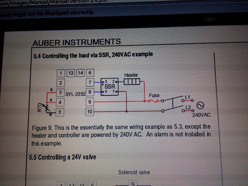
as i was looking on some forums I found a suggestion to lookup the manual for the Syl-2342 PID controller and check out the instructions for a cross reference (since they are easier to follow)… Here is a link to the manual. Now I’m confused as ever… I think I may have my wiring all wrong? Any help would be much appreciated!!
“3.4 For first time users without priorexperience with PID controllers, the following notes may prevent you from making common mistakes.
3 . 4 . 1 Power to the h ea t e r does not flow through terminal 9 and 1 0 of the
controller. The controller consumes less than 2 watts of power. It only
provides a control signal to the relay. Therefore, wires in the 18 to 26 gauge
range should be used for providing power to terminals 9 and 10. Thicker wires
may be more difficult to install.
3.4.2 The control relay outputs (for SYL-2342), -AL1 and AL2, are “dry†single
pole switches. They do not provide power by themselves. Please see Figure
6, 7 and 11 for how they are wired when providing a 120V output (or when
output voltage is the same as the power source for the controller). If the load
of the relay requires a different voltage than that for the controller, another
power source will be needed. See Figure 10 for examples.
3.4.3 SSR output power does not come from the input of the SSR. The output
of the SSR is a single pole switch between terminals 1 and 2 of the SSR. The
input of the SSR is for control, or triggering the SSR. (Please note we are
talking about the SSR itself, not the SSR control output of the controller).
When switching a North American 240V AC power, the heater will be live
even when the SSR is off. Users should install a double pole mechanical
switch to the power input.
3.4.4. For all controller models listed in this manual, the power is controlled by
regulating the duration of on time for a fixed period of time. It is not controlled
by regulating amplitude of the voltage or current. This is often referred as time
proportional control. e.g. If the cycle rate is set for 100 seconds, a 60% output
means controller will switch on the power for 60 seconds and off for 40
seconds (60/100=60%). Almost all high power control systems use time
proportional control because amplitude proportional control is too expensive
and inefficient.”So I should have live power going directly to the output terminals of my SSR? *so confused*
check it out…
Like I said… its kinda complicated but any help would be appreciated =)
12/08/2013 at 10:49 am #15971I it does not look quite right but I am not a sparky having said that I would recon end you use one for this. If funds permit there is afire risk if it is not right ; I would pay a sparky for peace of mind and to cover your household insurance .
I believe it has gone extreme in the UK in that if you are not an electrician it is against the law to wire even a three pin plug I believe health & safety and all that.
I bought an Ikea oven for my apartment and went to fit it – no instructions so I went on line I found scraps
of info mainly for non European markets then as I dug deeper I found that it was highly recommended to use an electrician their charges are capped I think it cost about 60€ but it was worth the pease of mind.12/13/2013 at 6:39 am #15990Hi Razor:
In a former life, I was an electrical engineer working on these things quite a bit.
So did you get this thing working yet?
It doesn’t look like the diagram on the side of the unit matches up with the wires in the photos or maybe not to the wiring diagram shown in the photo of the instructions. The diagram on the unit shows power entering at terms 1 & 2 while the instruction diagram says terms 9 & 10. That said, you gotta go with the diagram on the unit.
I can’t tell from the photos if there is a jumper (as is shown on the diagram) between terms 9 & 12. I also can’t tell from your photos if the power wiring is right. If red is red and black is black (no reversal in the wiring) there should be a connection somewhere between the black power line coming to the back of the PID unit, the black wire coming to the SSR and also a black wire going to one end of the heater. The red wire leaving the SSR should be feeding the other end of the heater. If all that is correct, it looks like it’s wired up right and you gotta look for a bad component.
Do you have a volt meter?
12/13/2013 at 7:14 pm #15995Hi Razor:
In a former life, I was an electrical engineer working on these things quite a bit.
So did you get this thing working yet?
It doesn’t look like the diagram on the side of the unit matches up with the wires in the photos or maybe not to the wiring diagram shown in the photo of the instructions. The diagram on the unit shows power entering at terms 1 & 2 while the instruction diagram says terms 9 & 10. That said, you gotta go with the diagram on the unit.
I can’t tell from the photos if there is a jumper (as is shown on the diagram) between terms 9 & 12. I also can’t tell from your photos if the power wiring is right. If red is red and black is black (no reversal in the wiring) there should be a connection somewhere between the black power line coming to the back of the PID unit, the black wire coming to the SSR and also a black wire going to one end of the heater. The red wire leaving the SSR should be feeding the other end of the heater. If all that is correct, it looks like it’s wired up right and you gotta look for a bad component.
Do you have a volt meter?
It doesn’t match up, you are exactly correct… This is because the mypin instructions were pretty horrible so I found a diagram from the Syl PID controller which explains things much better. I’ll take a pic of the instructions for the mypin controller in a few hours and post it up.
I don’t have a jumper connected yet… I have to get out there with my meter and the diagram and try to figure this thing out. I didn’t think the red/black mattered? Both of my hot wires (red & black) are going into the pid controller in ports 1 & 2 and they have about 110v on each of them. The last diagram I posted seems to be the correct theory, right? I will try to go off of that.
12/14/2013 at 3:44 am #15998So it sounds like your heater still isn’t working and we need to chase this culprit down…
I think your problem is in the power wiring. Trace your power leads, making sure that the red wire (L1) is connected to one controller power terminal and also to one terminal of the heater element. Then trace out the other power line – the black wire (L2); making sure it connects to the other controller power terminal and also to terminal #1 on the SSR. The remaining power wire runs from Terminal #2 of the SSR to the remaining terminal on the heater element. I think you may be missing one of these connections.
Also:
Since you have a 240 V system, you should have fuses or circuit breakers in both power lines.
The jumper in the heat sensor circuit is important. The sensor is a thermistor – a resistor which changes resistance with a change in temperature. To calculate the actual resistance of the sensor and not include the resistance of the wire (the wires could be quite long), they measure the resistance of the wire going to and from the sensor. They do this by running the extra wire to the sensor, then measuring the resistance of the run of these two wires. They then subtract this resistance from the total sensor circuit resistance and viola! they have the actual resistance of the thermistor. Very interesting,if you’re into this, but probably not your problem. If the jumper were missing, the controller would probably show a fault. The manufacturer’s instructions should explain this.
Now, the Solid State Relay… This is just a transistor version of a single-pole relay. Terminals #3 and #4 are low-voltage inputs. Any voltage coming in to these terminals (usually between 5 and 32 volts DC, in most cases 12 or 24VDC) will energize the “relay coil” which then closes a “contact” between the output terminals #1 and #2. By the way, the wires going from the controller to the SSR needn’t be large at all – 20 gauge would be fine.
The SSR has a metal base which is intended as a heat sink. Depending on the load (how many watts the heater is) it would be best if it were bolted (or sheet-metal screwed) to the floor of the cabinet to help dissipate heat.
So trace out the power wiring and then we’ll start checking voltages.
BTW, I installed a similar system to warm the hardwood floors in my home. Instead of heaters, I’m controlling water circulation pumps.
12/14/2013 at 6:23 pm #16002Thanks TC, you’ve been such a big help! I got it working! I did basically as you said… The problem wasn’t the actual wiring to the pid controlleror ssr vbut rather the wiring before that point (which I just rearranged). I basically had to trace down where my heating coil wires were (the red and black ones that went to both sides of each heating coil – in my case there were 2 of them) and then I could hook everything up the way it needed to be.
My mistake was that I was assuming that my new electronic PID controller switch was going to be wired similarly to the old switch, which basically had 2 hot wires, a switch in the middle, then the two output wires that would be activated when the switch turned to the “on” position. This was a flaw in my thinking and I realized as much 🙂 my brother in law actually came over and we figured it out together.
Now I just have to figure out the settings… I will say that I set the “set value” range to 100 degrees to test it, but the temp kept climbing past that value… Not sure why. If I hit the “set” button from the main display, It reads “100” when it’s getting hot and as it gets up to temp that value starts dropping, but very slowly. I figure that this is the percentage value of output to my heating elements so as it gets closer to temp it will back off how much power it puts out. I just don’t understand why it did not rapidly decline once the temp was reached?
12/15/2013 at 1:38 pm #16007Well, at last I’ve been able to help someone.
I don’t know how old your PID controller is, but most of the ones on the market have a self-teaching capability. They are programmed to watch how the load reacts (basically,they measure how rapidly the temp changes and how much it overshoots) and automatically adjusts its own settings. To do this, you may have to let it run freely for a while to collect enough data.
-
AuthorPosts
- You must be logged in to reply to this topic.