Advanced alignment guide
Recent › Forums › Main Forum › Product Announcements › Advanced alignment guide
- This topic has 189 replies, 22 voices, and was last updated 05/24/2016 at 3:13 am by
 M1rrorEdge.
-
AuthorPosts
-
01/13/2016 at 6:02 pm #30624
Glad to hear the advanced alignment guide is nearing production, Clay. I will definitely be buying one.
Unhelpfully, I don’t have any real feedback regarding the overall dimensions. Your proposed dimensions would fit all knives I have sharpened to date, so they seem reasonable to me.
Thanks!
~Dan
01/13/2016 at 7:56 pm #30625This is the best thread I’ve read in some time. I continue to learn so much here…
For my needs, the AAG would be very helpful. Clay, any idea as to when it will be available?
Thanks now.

Alan
01/14/2016 at 12:00 pm #30633Thanks for the feedback guys. Once we get the design finalized, it should take about a month to have them in production.
-Clay
01/15/2016 at 12:26 pm #30641Here are a couple new renderings of the AAG design:
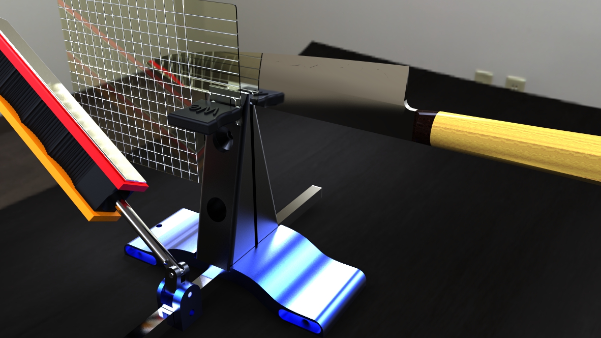
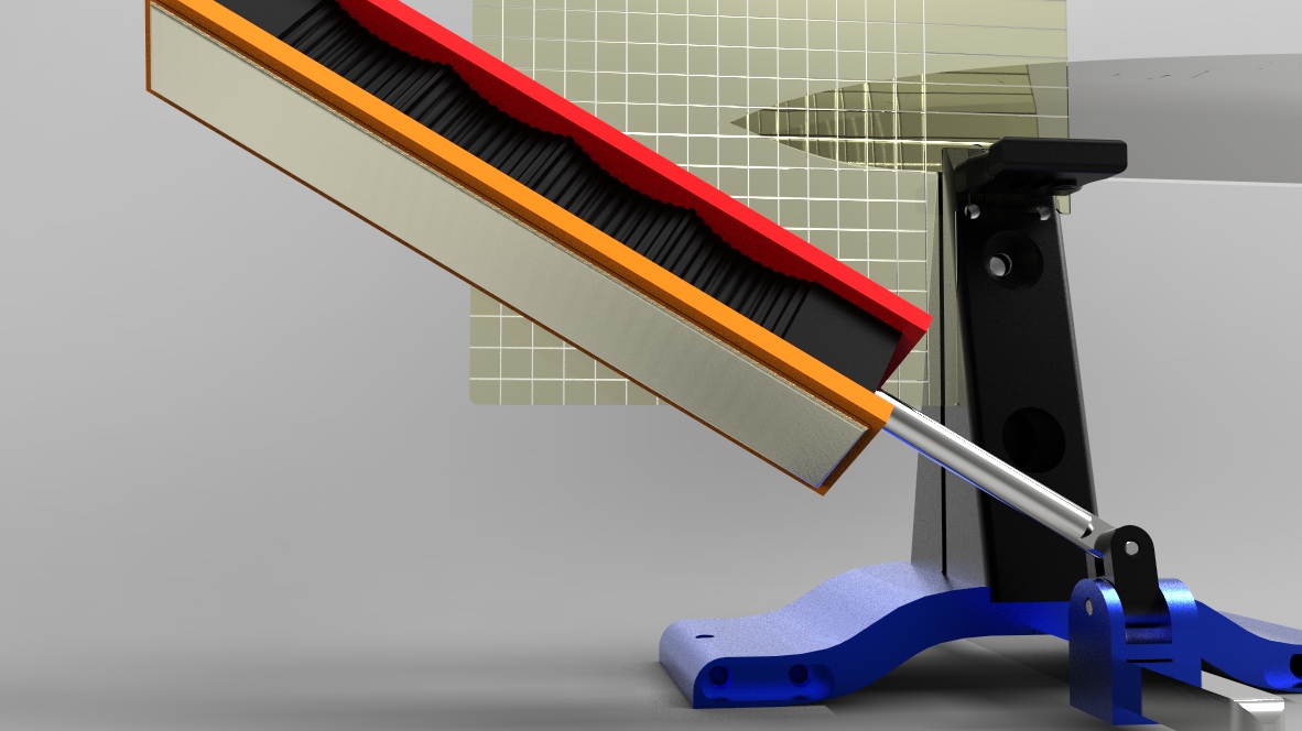
I’ve got some material on order to test it out and maybe expand it to the dimensions Mark requested. I’m having fun with the models and rendering software.
-Clay
Attachments:
You must be logged in to access attached files.
01/15/2016 at 12:30 pm #30644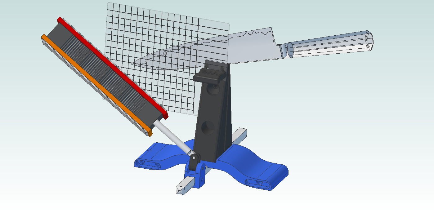
In this one, I have tilted the blade down to show how the tool can be used. I didn’t go through the whole process of setting up the materials for a new rendering:
-Clay
Attachments:
You must be logged in to access attached files.
01/15/2016 at 2:08 pm #30647Anonymous
Inactive- Topics: 14
- Replies: 427
Ive been afraid to post much in this thread..B ut I’m here every day to digest the conversation. Now this rendering has me a bit upset… was this blade just thown in the vice, or is this the optimum placement for this blade? You see, thisd isd how I see it… If you do not know exactly how to set up the knife, and you chart what you miigh think is correct, then all you will do is repeat a poor set up… Ive seen how the sharpie can identify the correct placement, but I also see that a close set up is not the correct set up. I can see that correcting a poor placement can be measured in thousands of an inch, or minutes of a single degree. So IM just not getting this whole thing… While I do not fully understand the correct set up, IM getting the idea, that a correct set up is very absolute. So Ill leave that portion for now until I get a better feel for the actual set up.
Now for the guide.. here are my thoughts.. I think you need reference marks across the top A, B, C, D , ect. and numbers in the left margin 1, 2, 3 etc.
so you would have coordinates for the tip, the belly, and a third point of reference ( not sure what that would be… ) then all you would have to do it take a side photo from your cell, put it into a folder on your cell, and you would have a digital image of the set up, not just a alpha numerical reference.
I think if the lines were colored in alternate black and white, both horizontal and vertical , you could easily follow the line to the number or alpha. If the lines are just clear or one color you could lose the reference point by jumping a line.
Just my thoughts
Bill aka ET
1 user thanked author for this post.
01/15/2016 at 2:47 pm #30648Ive been afraid to post much in this thread..B ut I’m here every day to digest the conversation. Now this rendering has me a bit upset… was this blade just thown in the vice, or is this the optimum placement for this blade? You see, thisd isd how I see it… If you do not know exactly how to set up the knife, and you chart what you miigh think is correct, then all you will do is repeat a poor set up… Ive seen how the sharpie can identify the correct placement, but I also see that a close set up is not the correct set up. I can see that correcting a poor placement can be measured in thousands of an inch, or minutes of a single degree. So IM just not getting this whole thing… While I do not fully understand the correct set up, IM getting the idea, that a correct set up is very absolute. So Ill leave that portion for now until I get a better feel for the actual set up. Now for the guide.. here are my thoughts.. I think you need reference marks across the top A, B, C, D , ect. and numbers in the left margin 1, 2, 3 etc. so you would have coordinates for the tip, the belly, and a third point of reference ( not sure what that would be… ) then all you would have to do it take a side photo from your cell, put it into a folder on your cell, and you would have a digital image of the set up, not just a alpha numerical reference. I think if the lines were colored in alternate black and white, both horizontal and vertical , you could easily follow the line to the number or alpha. If the lines are just clear or one color you could lose the reference point by jumping a line. Just my thoughts Bill aka ET
Thanks for the feedback ET. I did just tilt the blade randomly to illustrate how the user could align the tip to a specific coordinate for repeatability. I didn’t take time to put the coordinate system on these renderings, but you’re right that alphanumeric markings will be necessary. The rendering in this post: https://knife.wickededgeusa.com/forums/topic/advanced-alignment-guide/page/2/#post-30512 shows something similar.
As far as the optimal positioning being absolute, there is one setting for each knife that would give the most even bevels and would minimize angle change throughout the changing geometry of the blade. Anthony Yan did a wonderful job of describing the optimal placement in a post a while back. I’ll rummage around to see if I can find it. Even without his excellent math, it’s possible to get very close using a little trial and error and a sharpie. Once you’ve found the position that best suits your needs, you can slide the card in and record the coordinates for the knife tip and then be able to repeat that very easily in future sessions. I like your idea of snapping a photo for reference, nice and easy.
-Clay
01/15/2016 at 2:50 pm #30649ET – here’s the post I was thinking about: https://knife.wickededgeusa.com/forums/topic/geometry-and-kinematics-of-guided-rod-sharpeners/. I know you’ve been asking for a more technical explanation for knife positioning. I think you’ll get a lot out of it.

-Clay
2 users thanked author for this post.
01/15/2016 at 5:30 pm #30650Hi everyone. Newly registered.
It might be easier to use the top and front of the vise jaw to reference the plastic sheet instead of the alignment pins.
It would then rest right next to the blade and could be held with a binder clip.
Jerry
01/15/2016 at 6:47 pm #30651I like ET’s suggestion of alternate colors on the grid to help us keep things straight. With lines going on angles it could lead to visually jumping lines. Great thread, good discussion. I believe the guide will be very helpful.
01/15/2016 at 6:52 pm #30652actually meant the blade going across lines (angles) on the square grid.
01/15/2016 at 7:56 pm #30653Inactive- Topics: 14
- Replies: 427
ET – here’s the post I was thinking about: https://knife.wickededgeusa.com/forums/topic/geometry-and-kinematics-of-guided-rod-sharpeners/. I know you’ve been asking for a more technical explanation for knife positioning. I think you’ll get a lot out of it.
Thanks Clay, this is exactly what I needed…
This Link should be on the website for permanent reference. It makes things crystal clear.
01/16/2016 at 8:02 am #30658I like ET’s suggestion of alternate colors on the grid to help us keep things straight. With lines going on angles it could lead to visually jumping lines. Great thread, good discussion. I believe the guide will be very helpful.
I probably prefer simple black or white lines. The material is transparent, so you’ll see the background through it. To optimize visibility of the lines, a single contrasting color is best, I think.
Molecule Polishing: my blog about sharpening with the Wicked Edge
01/16/2016 at 10:58 am #30659I probably prefer simple black or white lines. The material is transparent, so you’ll see the background through it. To optimize visibility of the lines, a single contrasting color is best, I think.
Agreed. I think one color would work just fine.
Alan
01/16/2016 at 1:38 pm #30660I concede. I made up a couple of mock guides. With solid lines and multi-color lines. The solid line was much easier to read. Multi color was just to messy.
2 users thanked author for this post.
-
AuthorPosts
- You must be logged in to reply to this topic.