First off, it’s really annoying how when I copy and paste something here, even if I remove formatting in Word, it has all these formatting notations in my text… that being out of the way, and me having spent the time to clean this up, here you go. 🙂
So I have a Variable Frequency Drive that runs several motors (individually, not at the same time). In the picture below, you will see a bunch of red jumpers on a circuit board, one of those is going horizontal, the one below where it says “CL”. Where that jumper is there are a total of 10 pins, each measuring .025″ in diameter. I want to connect 22 gauge wire to each of those pins individually and run them out of my vfd to a remote rotary switch. The connectors I need will have to crimp/solder onto the wire, and then the other side of the connector will be female and slide down over the male pin and be a good fit. Any idea of what types of connectors these are an where I would get them?
* for those interested in what this is doing, basically the jumper connects each set of pins to enable you to run 5 different horse power rated motors – 2, 1.5, 1, 3/4, and 1/2 HP. So my rotary switch will allow me to change the HP rating for whatever motor I’m using on the fly instead of having to open up this box and manually change the jumper.
Thanks for any and all help

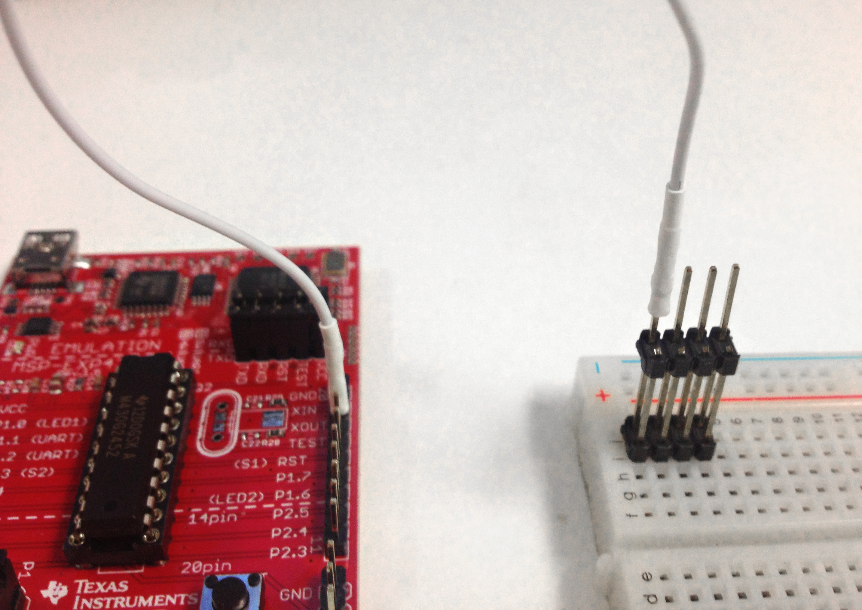
I already have the wire, I just need the connectors. It will look like this (as I am sure you are well aware =)

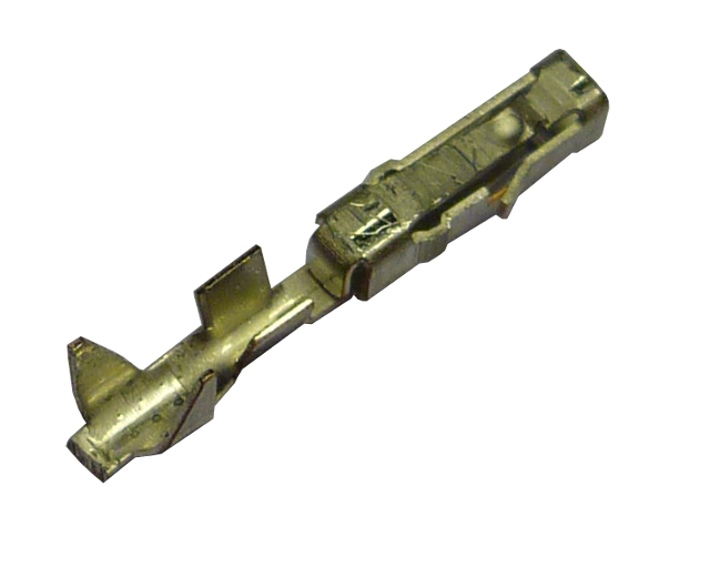
More close ups of what I’m looking for but don’t know what they’re called…


Here is a pic of the wire I was going to use… I got it from mcmaster carr High-Voltage Continuous-Flex Flat Cable. You think the signal would travel the 10 ft to and 10ft from ok? Is there a way to measure it w/ a meter to see if it would be strong enough?


