Protect the micro angle adjustment threads
Recent › Forums › Main Forum › Sharpener and Accessory Maintenance › Protect the micro angle adjustment threads
- This topic has 8 replies, 5 voices, and was last updated 01/03/2013 at 7:59 am by
Richard Green.
-
AuthorPosts
-
12/09/2012 at 2:53 am #7987
Here are some pictures to show you how to protect the threads on your micro angle adjustment ball joint.
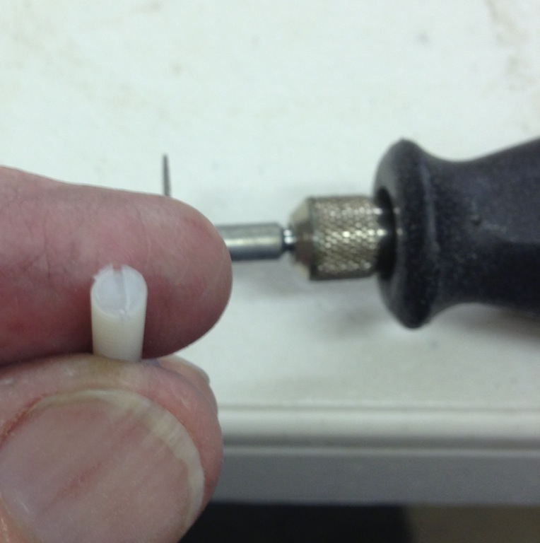
Get a nylon screw. I used an 8-32 from Lowes for 56cents. I know it is a smaller thread size but it will work easier.
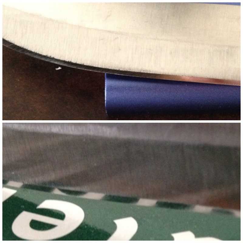
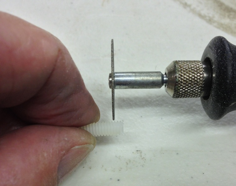
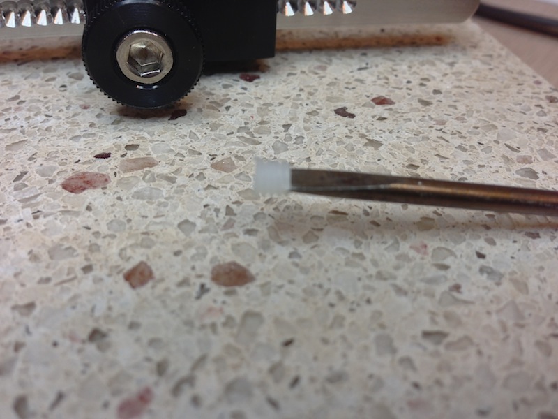
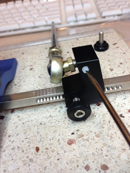
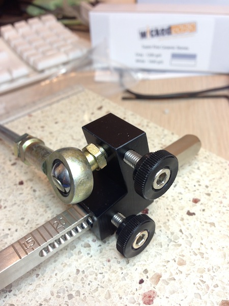
Use a dremel to cut a small notch in the end (pictures 1&2). Then cut off the end at about .140 or 3.5 mm ( pictures 3&4 ). Repeat the process to make 2 small nylon screws. Thread your new screws into the micro adjustment lock threads of the L-bracket until they stop ( picture 5 ). Then replace the 10-32 thumb lock screw and tighten down ( picture 6). This will protect the threads from getting damaged by the 2 screws jamming together. You may have to tighten it pretty tight the first couple of times until the new nylon threads compress but after that it works great and there will be no thread damage.
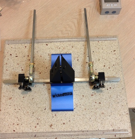
I also got some 5/16 self adhesive car door protector to put on the edge of my base to protect the arms and base from damage see (picture 7).
I hope this helps some of you.Mark
Attachments:12/09/2012 at 4:32 am #8001Hi Mark,
I’ll just embed your pics.


You could just roll in a nylon pellet?
I was going to use lead shot at one stage.I suggest you use a flat face screw now.
12/09/2012 at 4:59 am #8010Thanks for embedding the pictures.
I couldn’t find a small enough nylon pellet or rod so the nylon screw was the easiest way. I thought about grinding down the taper on the thumb screws but it isn’t deeded.
Thanks
Mark12/09/2012 at 5:01 am #8011Thanks for sharing.
12/09/2012 at 5:11 am #8014I was thinking of taking a slice out of the L-bracket and putting in a big/thin thumb nut to lock the stud.

Lower it down from the top, the stud goes through it.

I would put it on the back, but the stud is not long enough.
It only needs to adjust enought to meet the next angle dimple. (degree)
12/13/2012 at 6:07 am #8218I received my replacement L brackets with the 10-32 screws (thanks Clay). When replacing the old with the new, I did notice some quite visible deformation of the micro-adjustment threads on the ball arm. Rather than try to make an insert like Mark suggested, just went and changed out the clamping screw with 10-32 x 5/8 nylon socket cap screws. I got a pack of 40 for $5.49 at Grainger. Unfortunately, shipping was more than the pack of screws …. but it saved me the time and expense of driving 40 miles to my nearest large hardware store!!! They seem to work fine, so far, and will hopefully minimize further damage to the threads on the ball arm. And, with 38 left … shouldn’t have plenty of replacements for wear or breakage!
12/13/2012 at 6:32 pm #8228I just removed my micro adjust lock screws. I also wrapped plumber’s (teflon) tape around the heim/ball joint threads, which tightens it up enough so that you need the wrench to turn the micro adjuster (on the heim/ball join). Actually one of my joints was much tighter than the other, where you needed to use the wrench (and that was without the teflon tape). The other side could be easily adjusted by hand so I added a few wraps.
You’ll want to check how tight they are without the lock screws, and be conservative when adding the teflon tape; much better to put too little and have to rewrap than to put too much and jam it up (literally). 😉
12/15/2012 at 3:02 pm #8259Actually one of my joints was much tighter than the other, where you needed to use the wrench (and that was without the teflon tape). The other side could be easily adjusted by hand ….
Sometimes a loose thread could mean the pilot hole drill size used wasn’t correct (7/32″) and too much metal was removed, meaning the thread depth is then too shallow.
There are also small variations between brands and tap types.
A link below to explain.
“1. Determine the appropriate drill bit for the tap size you are using. If you make the hole too narrow, the tap will break under pressure and if you make it too big, the thread will be too loose for any screws that you use after you are done tapping.”
http://www.ehow.com/how_5623551_drill-tap-threads-metal.html
A metal thread insert may be a solution, but then you would need to drill out the lock screw hole.
My 2c.
01/03/2013 at 7:59 am #8565After assembling the new arms for the first time, I saw the beginning of thread deformation on the micro-adjustment screws.
I had some 6-32 nylon screws on hand, so I snipped off 1/8″ or so from the ends of two of them. I didn’t bother with slotting them because the “slugs” just slid into the holes. They seem to be doing the job nicely — no more thread deformation and when the thumbscrews are tightened down the micro adjustment screws don’t turn. It’s possible that I’ll have to replace the nylon slugs every now and then as they wear/deform/split from the pressure applied. But it’s cheap and easy protection for the far more expensive ball joints.
Seems to me the simplest solution would be to use a longer micro adjustment screw and a lock nut. The longer screw should protrude through the tapped access hole (on the side opposite the ball joints) enough so that a pair of lock nuts can be put in place when the micro adjustment screw is extended towards the vice as much as would be reasonable (equivalent to one mark on the beam scale?) I think this might work with one wrench to secure/loosen the lock nuts (as opposed to two, as suggested in another thread.) A nylock (aircraft nut) might work, too.
Another, less practical solution would be to enlarge the block so that the micro adjustment screw is always at least 1/4″ shy of the top of the access hole. That way, a thumbscrew could be inserted in the access hole and turned to hold the micro adjustment screw in place. It would have to be flat in order not to damage the hex head on the end of the micro adjustment screw.
-
AuthorPosts
- You must be logged in to reply to this topic.