Larger Knobs and Thumbscrews on the WE130
Recent › Forums › Main Forum › Sharpener and Accessory Maintenance › MODS › Larger Knobs and Thumbscrews on the WE130
- This topic has 22 replies, 10 voices, and was last updated 08/10/2019 at 4:47 pm by
Brewbear.
-
AuthorPosts
-
01/23/2019 at 11:14 am #49136
Anonymous
Inactive- Topics: 2
- Replies: 8
On the WE130, I have found the knurled nuts on the micro-adjusters and the thumbscrews on the L-brackets to be a little on the small side.
So I replaced the standard 1/2″ knurled knobs on the micro-adjusters with 3/4″ knurled knobs from Carr/Lane Manufacturers (part # CL-1032-TSJN). I had the knobs machined to a thickness of 1/8″ because of the relatively short threading on the micro-adjusters. Note – the 3/4″ knurled knobs that I purchased from Carr/Lane for the micro-adjusters were originally threaded for 10/32. I had the machinist change them to ¼”-28 (the threading on the micro-adjusters) when he made them thinner. tcmeyer’s post below has complete information on where to get knobs that are already threaded to 1/4″-28.
I also replaced the thumbscrews on the L-brackets with plastic 9/16” knurled knobs from MSC Industrial Supply (part # 06172308) that come with female metal inserts that are threaded to #10/32, the same threading as the L-brackets. Next I had the heads removed from one inch #10/32 socket-head cap screws, and had points machined onto the ends of the cap screws at 45<sup>0</sup> to match the points on the original thumbscrews. Finally I screwed the cap screws into the plastic knobs with a little epoxy to make sure they stayed put.
Then I added 1/4” nylon washers (True Value Hardware) to keep the knurled knobs from becoming loose.
To make it easier to access the new plastic L-bracket knobs, I used a piece of oak (Menards) to raise the vice and the Degree Bars relative to the aluminum base (the base stills needs to be beveled, finish sanded, stained and given a couple of coats of polyurethane varnish).
6 users thanked author for this post.
01/23/2019 at 2:55 pm #49147That is exactly my intensions to raise the sharpener up off the base a little more, fat fingers I have maybe. Larger nuts on the micro adjustments should give more leverage to tighten a bit more, the left side of mind tends to back off sometimes, this should help with that. Thanks for the info & part #.
01/23/2019 at 3:54 pm #49149Inactive- Topics: 2
- Replies: 8
More leverage is exactly why I went with the larger knurled nuts. I was also having problems tightening them.
But also try the nylon washers. My micro-adjusters haven’t loosened once since I started using them.
1 user thanked author for this post.
01/24/2019 at 5:19 pm #49157Inactive- Topics: 2
- Replies: 8
The 3/4″ knurled knobs that I purchased from Carr/Lane for the micro-adjusters were originally threaded for 10/32. I had the machinist change them to ¼”-28 (the threading on the micro-adjusters) when he made them thinner.
I was unable to find a knurled knob with the diameter I wanted that had the proper threading.
01/25/2019 at 3:37 am #49160I bought stainless steel knobs from McMaster ( part no. 60205K81 )which were already threaded for 1/4″-28. I then cut the hubs off with a hacksaw. This leaves a somewhat thicker knurled nut at 1″ diameter. I’ve had no problems tightening them without washers. I love the higher mass (rotary moment of inertia) as they spin very easily with a flick of a finger tip.
I put the hack-sawed faces against the brackets – I’m thinking maybe that’s why they lock up so nicely. A smooth surface against a smooth surface is more likely to slip free.
In the following photo, the nut (knurled flange) shown against the bracket began looking almost exactly like the knob on the end of the micro-adjust screw, but without the set screw:

8 users thanked author for this post.
01/25/2019 at 7:55 am #49162Inactive- Topics: 2
- Replies: 8
Tom
Definitely missed those at McMaster Carr. They are also probably easier to use because of the even larger diameter. The good news is that, when the machinist machined off the hubs on mine, he didn’t charge me any more to rethread the knobs.I don’t think I could done as good a job as you did with the hacksaw.
Thanks
Rummels03/05/2019 at 8:48 pm #49631It’s next to impossible to keep those thumbscrews tight enough not to slip. I wish Wicked Edge would make an upgrade for this issue. We should have a system that stays locked down once the angle is verified and locked in place. This also happens with the micro adjustment thumb screw.
03/07/2019 at 5:13 pm #49644To elaborate on my micro-adjust knobs, I offer the following , more detailed info:
When the 2017 version of the Gen 3 Pro came out with the concentric jam nut (actually, it’s a screw), I was disappointed, as this arrangement is really just an addition to the micro-adjust screw, it only “jams” to the extent that the two screws are misaligned. As it is, if you tighten one, the forces applied will tend to turn the other.
Since I completed my upgrades, I’ve had at least six guys ask for details on the parts I used. Mods don’t cost Clay any of his business, and since Clay gave me permission to post it, I suppose this is as good a time as any. :
Ball joints:
McMaster sells a bunch of different grades of Internally Threaded Ball Joint Rod Ends, all in 1/4″-28. They cost anywhere from $3 to $14, or more. I’ve tried three or four different types and they all work fine. I saw off 1/2″ from the threaded end to give me a little more range or vertical motion. Since there’s a very small load at any given time, three turns of thread is sufficient for our uses. Here’s a couple of part numbers for you to look at: 60645K32, 2458K32, 6072K154 and 59915K42. The last one is stainless and the most expensive, at $14 ea.
Micro-adjust screw:
I buy a single 12″ length of stainless steel threaded rod, part number 98804A108. It costs a whopping $2.12. I cut it into four equal-length pieces (I have two rigs), so each side gets a 3″ long screw. I clean up the ends of each screw with a sander. One end should have a slight taper to the threads so the nut will engage the threads easily. I put a very small dab of epoxy (not so much it gets onto the outside of the ball) on the non-tapered end of each screw and set them into the hole in the ball joint. You don’t have to be concerned about alignment, as that’s the purpose of a ball joint in the first place. If there’s a bit of vertical movement as the screw is rotated, it won’t affect the angle more than a tiny amount, so there’s no need for concerned there, either.
Adjustment knob:
Staying with the stainless theme, I picked a knob with a knurled flange and hub, part number 60205K81, $7.10 each. It has a 1/4″-28 threaded thru-hole and a 1″ diameter knurled flange. Since we’re using the knob to turn the screw, we need a way to lock the knob to the screw. I prefer set screws and wouldn’t you know it, they don’t offer knobs with set screws AND threads. So I drilled and tapped the hub for a 8-32 set screw. I filed a flat spot on the screw for my set screw to tighten against. This reduces the chances of damaging the threads, as I want to be able to disassemble the parts if necessary.
If you don’t have a drill/tap, you can use a regular 1/4″-28 nut to jam-lock the knob to the screw. It costs you a little bit of adjustment range, but there’s plenty to spare. You can position the nut at either end of the knob. See the following photo for the jam nut arrangement, showing the outboard position:

Locking nut:
Here, I used the same part as the adjustment knob, but I sawed off the hub with a hacksaw. In the final installation, I threaded the nut with the rough saw-cut side against the micro-adjust bracket. I think this helps to “cock” the nut on the threads, thereby helping to lock the screw threads against the bracket. I was very pleased with the “feel” of the knurled nut, as the higher rotary moment of inertia lets me flick the nut with a finger tip to spin it on the screw.
Hub label (not shown in above photo, sorry):
This is an important part of the mod, as it gives you instant feedback on how far you’re actually turning the adjustment screw. I don’t recall if I used Word, Excel or Autosketch, (give me a break! I’m 74!) but the intent is to create a simple table, strip or whatever you want to call it. It’s 1/2″ wide and almost exactly 2″ long, with numbered segments from 0-9. I glued the label to my hubs with wood glue, but any adhesive which won’t gunk up the knob or paper is fine. I just grabbed what was handy and I’m sure that you’ll find something better. Protect it with a strip of clear packing tape. Paste a bunch of extras on your page before sending it to your printer. On most of my setups, each number correlates very closely to about 0.03 degrees. I placed the zero directly over the set screw so I wouldn’t have to wreck the whole label looking for it.
Notes:
Obviously, you can substitute any of a number of materials for some of the parts. The knob is available in steel, aluminum or brass. I even bought a pair of nylon (chemical resistant) rod end ball joints, but haven’t tried them yet.
In case it isn’t obvious, you’ll need four knobs and two ball joints.
I’ll be glad to answer any questions you might have.
-
This reply was modified 5 years, 1 month ago by
 tcmeyer. Reason: Clarity
-
This reply was modified 5 years, 1 month ago by tcmeyer.
-
This reply was modified 5 years, 1 month ago by tcmeyer.
-
This reply was modified 5 years, 1 month ago by tcmeyer.
9 users thanked author for this post.
03/10/2019 at 8:23 am #49669I am the “anonymous” author of the first posts at the start of this conversation (a problem with my login caused me to be disconnected from all of my past posts).
I have not had a single instance where the micro-adjusters or the L-bracket thumbscrews have become loose since I made the modifications that I have described.
Note that I have also suggested to the folks at Wicked Edge that they make the threaded portion of the micro-adjusters longer, so they can accommodate a larger lock nut and/or plastic washers.
08/03/2019 at 6:08 pm #51316I bought a set of Ed Kenny’s adjusters, I found them a picture of them in one of Dales’s postings. The larger knobs and longer adjuster screws make making micro-adjusting an angle with an angle cube a breeze, while saving a lot of time. I sure wish WE would make Ed’s large knob and adjustment setup standard on all of their products.
2 users thanked author for this post.
08/06/2019 at 3:44 pm #51406It’s next to impossible to keep those thumbscrews tight enough not to slip. I wish Wicked Edge would make an upgrade for this issue. We should have a system that stays locked down once the angle is verified and locked in place. This also happens with the micro adjustment thumb screw.
I agree, I’ve got a small fortune in my Gen 3 Pro and I have the same issue as everyone else. I use a set of small channel locks to tighten everything down, definitely a design flaw.
08/06/2019 at 5:58 pm #51417The attached picture show’s Ed Kenny’s adjusters. It’s not my setup, and I don’t remember where I grabbed the picture, I think that I was looking at something from one of Dale postings, which led to this picture. So, I give credit to whomever’s setup I’m showing. I can say that using Ed’s adjusters, once I’m locked in, nothing has loosened or changed.
Attachments:
You must be logged in to access attached files.
5 users thanked author for this post.
08/06/2019 at 7:09 pm #51423here’s Ed K’s set-up for the Gen 3 Pro:
Ed K is forum member: NotSharpEnuff
Marc
(MarcH's Rack-Its)Attachments:
You must be logged in to access attached files.
3 users thanked author for this post.
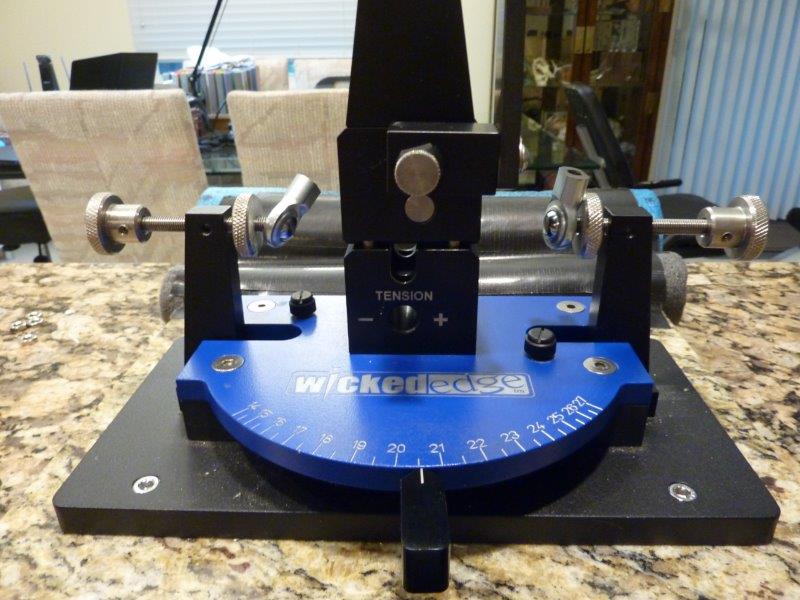
08/07/2019 at 2:37 am #51427Marc: How is that tension indicator on the near side of the vise? Is that a new feature from WE?? Kinda looks like the vise stack isn’t bolted together.
Mike? That’s a cool looking lamp!
Ed?? Is it yours? BTW, thanks for putting these mods out there. It helps my ego late at night.
1 user thanked author for this post.
08/07/2019 at 5:39 am #51429Tom,
The set pictured above is the implementation of your mod with all stainless parts. My adaptation is to use the plastic 1″ knobs with jam nuts.
The cost of all stainless parts and the labor cost to cut the barrel off of two knobs and tap the other two was prohibitive for me to make for other members. I did make a four sets for Marc’s rigs and three for my vises before I found the plastic knobs. Even though I have stainless, I’m using the plastic knobs for 90% of my sharpening.
Making the mod with the plastic knobs, I still spend close to three hours making a set.
Ed K.
-
AuthorPosts
- You must be logged in to reply to this topic.