Help on interpreting goniometer results
Recent › Forums › Main Forum › Techniques and Sharpening Strategies › Help on interpreting goniometer results
- This topic has 10 replies, 6 voices, and was last updated 05/07/2012 at 4:56 pm by
Anthony Yan.
-
AuthorPosts
-
02/06/2012 at 9:34 am #1562
Hi all,
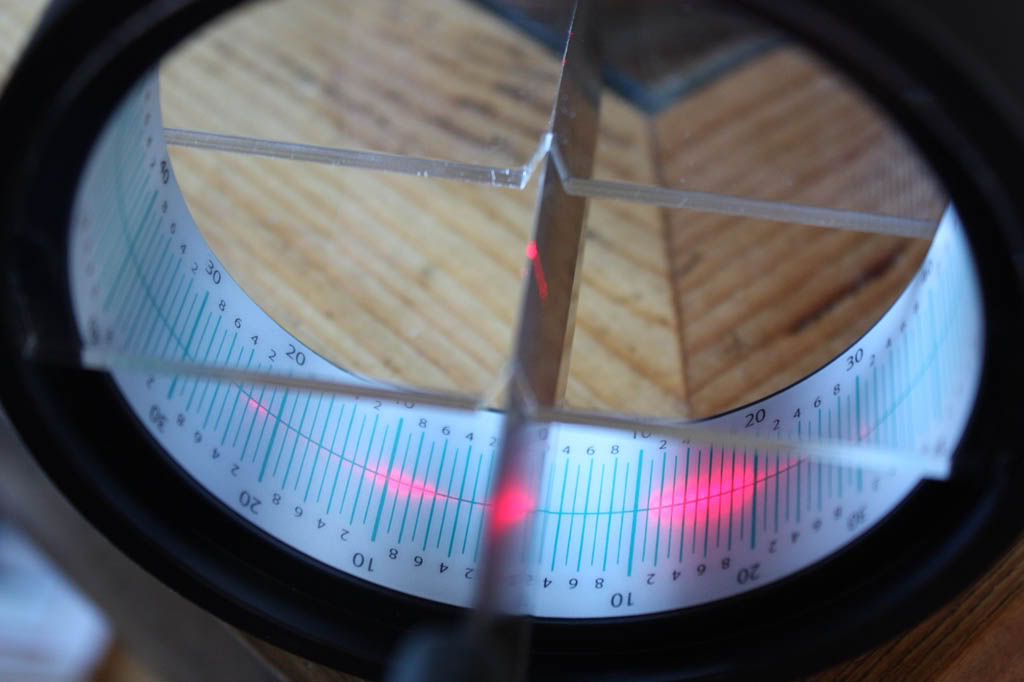
I’ve got a goniometer that aids in determining the angle at which a knife has been sharpened. It works quite well for knives with a flat grind, as for example my Swamprat Ratmandu:
The edge has got an angle of about 20 degrees per side.
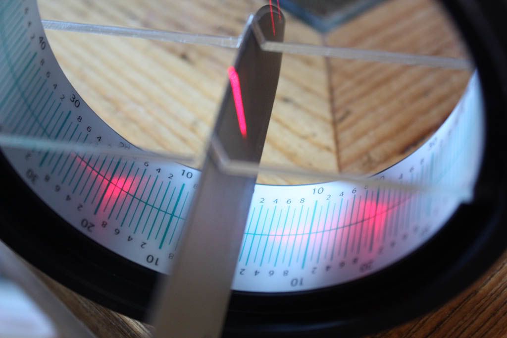
It also works quite well for thin knives with a convex grind, However, I cannot interpret the results the goniometer gives for a thick knife with a convex grind, my Fallkniven A1:
Can you help me interpret what my goniometer tries to tell me?
Thanks!
Molecule Polishing: my blog about sharpening with the Wicked Edge
02/06/2012 at 10:03 am #1564Hi Mark
I have had similar problems with the goniometer…I believe that the problem lies in the fact that the meter requires a flat facet to reflect the laser so it points to the correct reading. In a fully convexed blade, as the edge approaches zero the job for the meter becomes more and more difficult until a point is reached near zero when the laser reflects not only from the actual edge but even more from the steel at the base of the edge.Big sprays of red laser light all over the dial.
The reading I see there is very unclear but my best guess is between 4 and 6 degrees. You might try the following…turn the knife in the slot so it rests flat on one of the V sides…take a reading of the laser at its furthest reach…do the same with the knife lying flat on the other side of the V…if the readings are the same then you are at zero or approaching zero. If there is a difference e,g, one reading is 30 degrees and the other is 35 degrees then the angle is 5 degrees.
Having said all that I may be full of baloney. I will trust that those with more scientific minds than mine will see this just that or maybe not!!:whistle:Leo the nut case LOL!
02/07/2012 at 6:40 am #1567Hi Mark
I have had similar problems with the goniometer…
Sorry. guys. but I’ve never used one
I believe that the problem lies in the fact that the meter requires a flat facet to reflect the laser so it points to the correct reading. In a fully convexed blade, as the edge approaches zero the job for the meter becomes more and more difficult until a point is reached near zero when the laser reflects not only from the actual edge but even more from the steel at the base of the edge.Big sprays of red laser light all over the dial.
By ‘edge approaches zero’, do you mean as the blade width approaches zero as it gets closer to the very edge?
The reading I see there is very unclear but my best guess is between 4 and 6 degrees.
On one side, but looks indeterminate on the other. Is there a chance the knife was not ‘straight’ in the V?
You might try the following…turn the knife in the slot so it rests flat on one of the V sides…take a reading of the laser at its furthest reach…do the same with the knife lying flat on the other side of the V…if the readings are the same then you are at zero or approaching zero. If there is a difference e,g, one reading is 30 degrees and the other is 35 degrees then the angle is 5 degrees.
Not following here.
Having said all that I may be full of baloney.
Don’t think so. Is there a chance that the convex edge was simulated by sharpening 1° at a time? There seems to be step-changes to the laser light at about 1° increments. Could be illusion. The right side with bigger splash might indicate that the sides are asymmetric or the knife isn’t aligned with the V. CATRA does have other models that are for thicker knives. Could be that this one is too thick for this model
I will trust that those with more scientific minds than mine will see this just that or maybe not!!
Trust no one…02/08/2012 at 7:52 am #1572Thanks guys, for responding so quickly. (And for even calling Don 🙂 )
I guess I’ll have to live with the fact that my knife is too thick for exact results with the goniometer. Depending on how I hold the knife exactly, the light pattern is quite different: just a tiny bit of a degree already makes a world of difference. And there must be some unevenness in the knife, because the patch of light on the right (around 15 degrees) is consistently larger than the patch of light on the left (around 9 degrees).
You are probably right that these large patches of light are just reflections from anywhere on the blade. I was puzzled for some time, thinking: “a convex edge varying from 10 degrees till 28 degrees, that cannot be rightâ€. But now I come to think of it, the 28 degrees (in the photograph 22 and 31 degrees, but twice 28 when I slightly twist the knife) must be the dullest angle of the edge. And since it is convex, that must be the final angle of the edge of the blade. Does this make sense?
I also mailed Fallkniven with the question what the angle is of the final edge. They answer quite nicely every time. But the mail exchange is getting sillier and sillier. I ask them the angle and they respond with more and more detailed explanations on how to sharpen a convex edge :-). They are really worried I am going to end their beautiful convex edge with a guided sharpening system :-).
Molecule Polishing: my blog about sharpening with the Wicked Edge
02/08/2012 at 9:59 pm #1576From the convex picture, it looks like the knife isn’t exactly quite perpendicular, which would account for the wide reflection on the “right” side and almost nothing on the left.
Also, even if it is convexed, the edge of the edge should still split the beam, even if it spreads it out as in right side of the convex. The highest reading should be the edge angle, while the convexing of the bevel should produce the spread of lower angles. (Don’t forget, while the edge may approach zero degrees, the actual edge angle increases on convex grinds).
I’d play with the knife position on the Falkniven a little more.
02/09/2012 at 5:17 am #1580From the convex picture, it looks like the knife isn’t exactly quite perpendicular, which would account for the wide reflection on the “right” side and almost nothing on the left.
Also, even if it is convexed, the edge of the edge should still split the beam, even if it spreads it out as in right side of the convex. The highest reading should be the edge angle, while the convexing of the bevel should produce the spread of lower angles. (Don’t forget, while the edge may approach zero degrees, the actual edge angle increases on convex grinds).
I’d play with the knife position on the Falkniven a little more.
I agree with Tom.
-Clay
02/09/2012 at 7:34 am #1582Thanks guys! You’re right the knife position is not optimal. I did manage to get a somewhat optimal knife position (however, without a third hand, I didn’t manage to photograph that) and then the light marks furthest from the knife are at about 28 degrees on each side. The large patch of light at the right remains there.
An acquaintance of mine also mailed Catra (makers of the goniometer) and got a response from them. Nice guys! (And of course their goniometer can do a large convex knife 🙂 .) This is their response:
Extent of LH edge polish 21 to 23° convex Extent of RH edge polish 21 to 31°
The actual angle is read along the mid position line. Note that the blade is not centrally located it appears to be offset by 2-3° to the RH side, so the actual readings need to be adjusted by this minus on the RH and plus on the LH The result of this is typical of edge polished blades. Whilst the primary grind was intended it appears to be around 32° ( 12 +20) at the edge, the subsequent polishing has actually taken the final edge angle to 54° (23+31) included angle. During edge polishing high sharpness levels can be maintained if the polishing angle is the same or slightly more than the primary grind angle.
I don’t understand everything they say (21 to 23° and 21 to 31° ?), but I am happy they conclude the final edge angle should be about 54° inclusive. That is almost the 28 degrees per edge I inferred.
Molecule Polishing: my blog about sharpening with the Wicked Edge
05/07/2012 at 1:53 am #3060It took me a while to respond, but finally I had time to figure out the real angle of the edge of the edge.
And boy, was I wrong. That Fallkniven A1 is sharpened a lot more acutely than you’d probably think for such a big knife. The true angle is… 13.5 degrees :woohoo: . However, if you consider them carefully, the goniometer readings do make sense.
Sharpening the A1 on the WEPS involved some challenges, too. But I conquered them and now this knife shaves arm hair again
 .
.You can read the full story on my blog[/url].
Molecule Polishing: my blog about sharpening with the Wicked Edge
05/07/2012 at 3:06 pm #3068I haven’t time just now to explain everything I want to. So here is a brief sketch of what I understand. Later on, if I have time, I’ll make a more detailed post.
For now, let’s pretend the knife is a perfect wedge, meaning a perfect V-edge without any convexing or hollow-grind (it isn’t, but let’s understand this case first):
If you remember:
(1) Your ray-optics from high-school
(2) Your 2d plane geometry from high-school
Then you can work out that the angle subtended by the two reflected beams are twice the total included angle of the knife. Later if I have time, I’ll make another post to show the mathematical proof; it’s fairly straightforward.If you don’t remember (1) and (2), Prof. John Verhoeven works out the math for you in the Appendix of his tech report on knife sharpening (he talks about building a laser goniometer for knife edges based on a laser pointer):
http://www.mse.iastate.edu/fileadmin/www.mse.iastate.edu/static/files/verhoeven/KnifeShExps.pdfHere is one extreme examples that should make sense to everyone: If your knife has an included angle of 90 degrees (super blunt!) then the two reflected beams will be 180 degrees apart. Notice that 2*90 = 180. It turns out this formula works in general: 2*(inclusive angle of the knife edge) = angle between the two reflected beams. This will be true so long as the laser reflects off of both sides. If you turn the knife so far that one side of the bevel is in the shadow of the laser, then this is no longer true.
The most interesting part of this result, is that the angle between the two reflected beams is unaffected by small twists in the knife’s orientation. By twist, I mean a rotation through a line along longest axis of the knife.
There are some complications both from fine-scratches in the knife edge, as well as curved surfaces such as convexing or a hollow-grind. In the simple analysis sketched above, we ignore these additional complications. However, we may have to deal with them in practice. I’m still in the process of playing around to gain more practical experience with this. But for now, the math is pretty clear to me.
Currently, I’m very busy working out extremely detailed mathematics of guided sharpening systems and knife geometry. I also hope to build my own laser goniometer for measuring knife angles. This is a ton of stuff. Part of it is actually just doing all that, but it seems that explaining all of that in a good way might be a huge amount of work as well. I hope to have stuff for you guys in the coming week or two.
Sincerely,
–Lagrangian05/07/2012 at 4:28 pm #3069Hi Anthony,
Great to have someone knowledgeable in this area as well!
Theory does not only work nice in theory, but also in practice, for the goniometer.
If you have a knife with a flat bevel on top of a blade with sides of 0 degrees, it is quite easy to read the results. See the picture of my Ratmandu in my first post.
One thing that complicates the use of the goniometer is that it usually shows multiple patches of light: usually two per side. This may be due to the fact that the laser isn’t a perfect point laser. The patch at the lowest angle is usually, I think, due to some laser light creeping past the edge (so not being reflected by the edge) and hitting one of the sides of the blade, which then reflects it. You can see this in the picture of the Ratmandu from 4-17 degrees.
A second thing that complicates the use of the goniometer is that the light reflected from the edge usually does not end up in one point (or line), but makes a patch. This may be due to the fact that the edge isn’t a perfect flat surface, but contains scratches. In the picture of the Ratmandu, the reflected light is between 17 and 23 degrees. It is quite a step to conclude from that that the angle per side is 20 degrees.
And, as the remainder of the posts are about, if the blade does not have 0 degree sides and a flat edge, the reflection patterns can be much more complicated. In case of the Ratmandu, which not only has a convex edge, but an entirely convex blade, it was the patch of light at the lowest angle that represented the angle at the edge of the edge.
The most interesting part of this result, is that the angle between the two reflected beams is unaffected by small twists in the knife’s orientation. By twist, I mean a rotation through a line along longest axis of the knife.
This is true and this is why the 13.5 degrees per side makes sense for the A1 (included angle 27 degrees). However, the exact patterns of multiple patches vary wildly even with small rotation twists.
Molecule Polishing: my blog about sharpening with the Wicked Edge
05/07/2012 at 4:56 pm #3070Hi Mark76,
Right… I think I’m aware of all the effects you mentioned. Just don’t have time to go into all of it right now.
If you look at Verhoeven’s notes (early chapter(s) plus appendix I think), you will see that he talks about multiple-faceted knife edges on the laser goniometer. So the laser shines on both the micro-bevel and the back-bevel. So typically, you get a total of four spots (two on each side).
Normally, the multiple facets (micro bevel, back bevel, and then the side of the knife) form a convex polygonal cross section. So the microbevel has the largest included angle, and deflects the light the most, producing the widest two spots. Next, the included angle of the back-bevel is a bit smaller, and creates two spots which are closer together. Finally the sides of the knife have the smallest included angle of them all, and creates the spots which are closest to gether. In this example, there would be a total of six laser spots (three on each side, from microbevel, back-bevel, and the side of the knife).
If the cross-section of the knife is not convex (ie: a hollow grind), then the order of the spots can be changed around.
Maybe (?) one way to avoid confusion is simply to cover the sides of the knife with black tape, then the reflections will only be from the micro-bevel and back-bevel? Don’t know if this works well in practice or not.
Curved surfaces act like having a million little faceted bevels. So you get a “smear” of spots. This is interesting, but makes things harder to understand. The “smear” is caused by two things, I think. The first is a curved bevel (such as a convex bevel). The second is scratches and unevenness in the surface. Ignoring the surface-scratches/texture, let’s assume the convex edge has a mirror polish. Then the smeared out reflections represent the range of angles along the convex bevel. Each point in the smear, can be thought of as representing the angle of an infinitesimal tiny bevel facet (where the smooth convex bevel is thought of as being composed of an infinte number of tiny facets, just like a circle can be thought of as a polygon with an infinite number of sides).
Sorry, leaving out some details, and I’m not explaining things very well. But I think this is enough that all the details can be figured out without too much trouble. If not, I’ll have a more detailed post for you guys.
In the goniometer that I want to build, I’m hoping to use some optics to shrink the diameter of the laser beam, so that you are only checking the angles for a small spot on the knife. Not sure about the pratical issues of this, but you could easily use a binocular which is say, 8x magnification, to shrink the beam diameter by a factor of 8. In a real lab, they have “beam expanders” that they could run backwards to shrink the beam, and they have fancy collimator lenses, etc. But all that’s too expensive, I’m going to use a pair of cheapo $20 binoculars. Just shine light into the main aperature, and out the eyepiece will be a thinner beam. You may have to play with the focus a bit, though.
btw, NEVER EVER (never never, ever ever) look into an optical instrument of _any_ kind when working with laser light. The optics can focus the power of the laser to an extreme degree, which can much more easily cause eye-damage than an unfocused laser. Remember, your laser pointers are “safe” under normal conditions; looking at a laser through optics is NOT normal!
The real issue I’m worried about is how to deal with smearing in the reflected beam that is caused by surface texture (such as scratch patterns). Right now, I’m thinking to take multiple measurements of the reflected beam, where the twist of the knife (along it’s long axis) is changed several times. There is the whole issue of precision versus accuracy in such measurements, where the smear due to surface texture is, in a way, kind of hurting our precision.
http://en.wikipedia.org/wiki/Accuracy_and_precisionIf the surface-texture were isotropic (ie: look like it was sand-blasted), then this is easier to think about. But the scratch pattern is not isotropic; it’s anisotropic, meaning it has direction (such as parallel scratch patterns) and will smear out the reflection in some directions more than others. The sand-blasted texture is, on average, uniform and directionless, so we can consider it to be basically isotropic, and it would (on average) spread out the reflection in all directions equally. I’m oversimplyfing slightly, but this is the easiest way I know how to give the general idea without going into the details of the bidirectional-reflectance-distribution-function (BRDF) etc.
http://en.wikipedia.org/wiki/Bidirectional_reflectance_distribution_functionFinally, there may be issues with the laser being a coherent light source with a sngle wavelength, and therefore revealing diffraction and interference problems more readily. I think this isn’t so much of an issue, but I’ve not experimented, so I don’t know.
So my main question is: how to tell the difference between smearing due to geometry (such as convexing) from smearing due to surface texture (such as scratch marks)?
Hopefully I have more free time this week (or next) to discuss and experiment with everyone and everything in full detail.
Sincerely,
–LagrangianP.S. Another way to get precise knife angles is to use a mold of the knife (say using epoxy). You then remove the mold, cut a cross section, and then take a photograph of the mold using a microscope. Then measuring the photo, you can get the angle rather precisely. For example, most USB microscopes have tools for measuring lengths etc. in the image. This method was mentioned by Phil Wilson, and I also think by Cliff Stamp and/or Ankerson (of http://www.BladeForums.com). But I think it was someone else (sorry that I forget who) in bladeforums.com who first tried it (he talked about using WD-40 as an anti-sticking agent and W-B Weld Putty as the epoxy for making the mold). Perhaps one could compare the results of the mold-method to the laser-goniometer to see what’s going on with the smeared out reflected beams?
P.S. My favorite joke for hobbyists who play with lasers above 5 milli-watts of power is a sign that reads:

You can buy this sign from United Nuclear:
http://unitednuclear.com/index.php?main_page=index&cPath=29_60 -
AuthorPosts
- You must be logged in to reply to this topic.