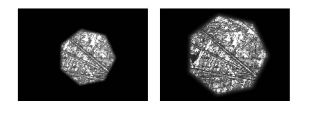
Comparison of Digital Imaging w/ Microscope
Recent › Forums › Main Forum › Off Topic › Comparison of Digital Imaging w/ Microscope
- This topic has 28 replies, 4 voices, and was last updated 05/24/2016 at 12:29 am by
CliffCurry.
-
AuthorPosts
-
05/20/2016 at 4:17 am #34095
I decided to just shoot a video to cover and show about 20+ images taken with 3 different devices. This is the best part for me, that keeps this “hobby” going n going. Its the exploration, learning, trying new things, sharing with you guys, and getting those special aha moments!
Here’s what I know for starters at this time….A USB scope is a great tool for quick edge examination. The more megapixels the better!!! Mine was $20 and its almost but not good enough. If it had just a bit more image resolution and a bit more magnification it would be my main use scope 90% of the time for basic daily use. As a very practical aside I hope to determine what magnification of quality is really needed for good daily use and then for close up inspections and then will give this old one to my kids. Eddie’s close communication with Dino-light is exciting to follow for that alone as it unfolds.
The video is still uploading so I will just talk a bit about what I hope to show and get feedback on from you guys. Microscope imaging at high magnification is no joke(duh!). There are hours of PHD guys giving lectures on it discussing “phases of light” and all kinda of crazy things. Differential diffraction??? I think these guys just like big words sometimes…LOL.
Two of the concepts that seem important(besides the light issue itself) is 1) Artifacts that happens when a digital device tries to “make” information in between 2 pixels of data and that kinda thing. It leads to geometric shapes sometimes like those grainy pictures of alien “moonbases”. This is where resolution and megapixels are important I think?
The second has to do with when 2 distinct real physical points are too damn close together and the ccd image sensor can’t pick then up. In that case, it just makes 1 fuzzy blob. This has to do with some crazy calculus involving the wavelength of light etc etc, but from what I could filter out in simple terms…the larger the CCD sensor the better.Keep that in mind when you watch the video below. You can bet I’ll be doing a lot more tests with the 2meg camera because it has a sensor on it that is 1/2in across. Compare this with my cell phone with a 16meg resolution in a tiny CCD form factor. I don’t have the answers but want to share as I’m trying to discover.
Heres the video finally…sorry about the audio a few numerical errors during recording.
3 users thanked author for this post.
05/20/2016 at 9:22 am #34102Nice video, Cliff.
Seeing the layer like sheets of metal at magnification was not just visually stimulating, something about brought together a few disconnected concepts.
If you are open to suggested testing, I’d be interested in seeing how those 220 grit teeth look coming off a heel-to-tip stroke compared to a tip-to-heel stroke.
On a regular saw blade, I can tell if it’s a push saw or a draw saw by looking at the teeth.
Would these knife ‘teeth’ show the same directionality?
And just for grins, because MirrorEdge showed us close-ups of the diamond stones and you showed us the 220 teeth, how about a picture of what the steel dust looks like at magnification?
Does it come off in sheets, in chunks, in crystiline pattern, in random swarf or complex geometrical shapes?
And, how does burnishing with leather move metal?
Seems rules are a bit different down there….
Keep going you guys, I’m trying to stay caught up!
Thanks for the great new depth of information in the science and the art.
~~~~
For Now,Gib
Φ
"Everyday edge for the bevel headed"
"Things work out best for those who make the best out of the way things work out."
1 user thanked author for this post.
05/20/2016 at 2:26 pm #34108Great video, Cliff. Can you tell us which camera is the 2MP camera? Is that the metallurgy scope (with a camera/CCD–is that in the eye piece?)? It provides really clear images. And what did you do with this camera to improve the lighting?
Also, can you elaborate a bit more on the phone camera with the eye piece? You get surprisingly good results with it. I know you wrote a post about it, but I still wonder how you get such images with a phone.
Molecule Polishing: my blog about sharpening with the Wicked Edge
1 user thanked author for this post.
05/20/2016 at 4:04 pm #34111Great video, Cliff. Can you tell us which camera is the 2MP camera? Is that the metallurgy scope (with a camera/CCD–is that in the eye piece?)? It provides really clear images. And what did you do with this camera to improve the lighting? Also, can you elaborate a bit more on the phone camera with the eye piece? You get surprisingly good results with it. I know you wrote a post about it, but I still wonder how you get such images with a phone.
Thanks Mark. The camera is a Motic 2000 2.0M pixel. It is being placed on the downtube of a trinocular head metallurgical scope, the MT1000T. I just got off the phone with Motic and they are being super helpful. Apparently I don’t have all the little adapters connected for optimal usage. I email this photo and am awaiting a return call when hopefully he will walk me through how to plug it all together as it should be for use in the downtube as opposed to the eyepiece position which it was set up for when I got it and didn’t know.
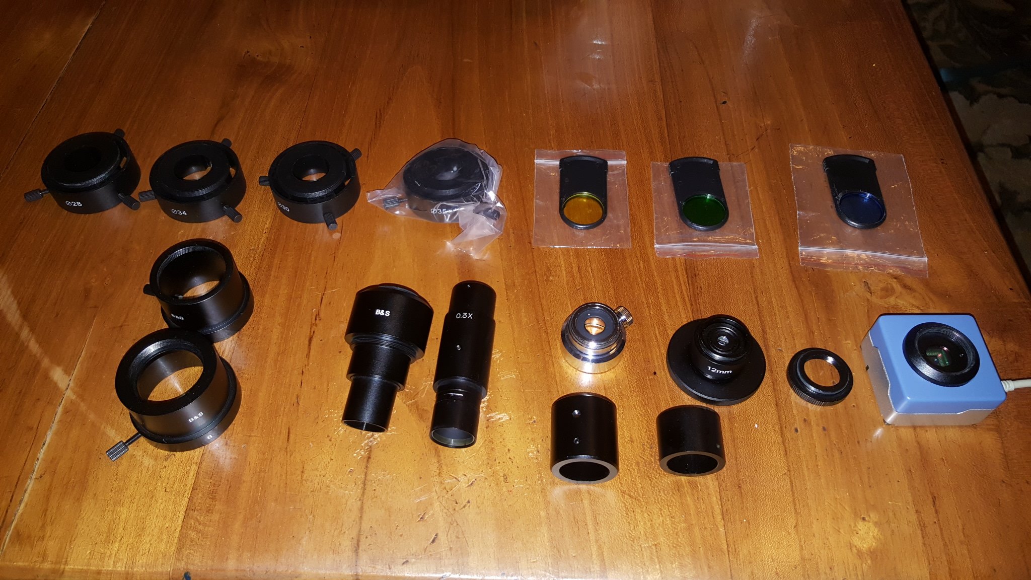
The specs on the Motic cam I could find are:
<1/2″ CMOS 2.0 Mega pixels (1600 x 1280) with USB 2.0 PC output With 16mm CCD lens 28, 30, 34 & 35mm eyepiece adapters B & S Adapter (Camera to eyetube)</td>The correct lighting, not including filters, involves a basic principle of modern microscopy called Kohler Illumination. The science of it is much harder then practical application. This video shows the concepts…I have been trying to match my hardware to something like this procedure. Keep in mind I’m in early learning phases of my own gear here and I just got the manual for my scope yesterday so the lighting setup procedure is also next.
The cell phone method is interesting but fiddly. The Carson adapter hold the phone in position(not very well) and I have it set for voice activation so can do no touch photos.
Its really to early to tell which is better, especially now that I know the Motic cam wasn’t installed correctly with all the adapter lens. Makes me really wonder if I could do better with the cell phone CCD sensor after playing around with others accessories as well.Mark understanding that I dont know a bit about what Im doing here, my current understanding is that mega pixels count but also the actual size of the sensor counts as well. Its a really good question that Ill ask in a few minutes to the motic tech guy!
Nice video, Cliff. Seeing the layer like sheets of metal at magnification was not just visually stimulating, something about brought together a few disconnected concepts. If you are open to suggested testing, I’d be interested in seeing how those 220 grit teeth look coming off a heel-to-tip stroke compared to a tip-to-heel stroke.
Roger that, Ive been a bit too eager to get testing and comparisons started. Once I get the equipment calibrated and working to its full focused potential then we can really compare and look at whatever comes up and be able to see usable results. The two thing I mentioned in the last post concern me greatly. As cool as some of the close up images so far have been to look at, I really feel that things that shouldnt be there are(artifacting) and things that should be there are not(pixel blurring). Getting the optics to truly match the CCD image sensor should put that behind us….More in a bit!
Attachments:
You must be logged in to access attached files.
05/20/2016 at 5:11 pm #34115Great stuff Cliff! The more I look and adjust my microscope the more I discover. I have ordered a micron calibration slide, because the Dino-light calibration target is not graduated small enough to properly measure and calibrate at these super high magnifications. Cliff is your scope “top lit”? Or, does it illuminate from under the stage? I see what your saying about the larger CCD sensor on the microscope camera compaired to a standard cell phone camera. I have a second biological microscope at home that has the larger format CCD camera, I’ll have to have my wife send that to me as well so I can see the differences. Dima had mentioned a adapter for a DSLR camera too. I’m kinda wondering what effect that would have too… Synergy Man you got me thinking now.
Eddie Kinlen
M1rror Edge Sharpening Service, LLC
+1(682)777-16222 users thanked author for this post.
05/21/2016 at 4:35 am #34118Almost done with the testing and setup with the scope. Getting results now that I feel represent if not the full potential of the scope then at least good enough for Government work…
I did one more full round of tests just between the Moticam 2meg & the Galaxy S6 cell phone 16meg. As it turns out I shot all of the cell phone pics with the resolution set down at lowest setting of 2meg by accident, but this should just make the comparison easier to pick a winner so I can move forward.
Its not totally scientific but I jigged a knife and didnt move it, Then took photos at x100, x200, & x400 with the Moticam, then switched to the cell phone and repeated with no light adjustment or color correction.
I did have a blue filter in place just because it helped with the Moticam, but I think it actually hurt the cell phone as they appear a bit too bright but otherwise the Moticams were coming out almost orange brown and too dark for details. Also the cell phone was zoomed in slightly to remove the “ring”.
Images below are photo stacked and I compared to originals for any artifacts or untrue features and they seem accurate. Lastly I did the entire process again for all photo stacks but this time first image adjusted the originals for contrast adjustments and then stacked again and compared those stacks to the originals. Lots of work….bottom line is the adjustments at least made then comparable, without that the moticams were to brown and just poor.
Heres is an attempt to overlay a side by side comparison at x100(the cell phones had to be resized manually to get a close to accurate zoom.
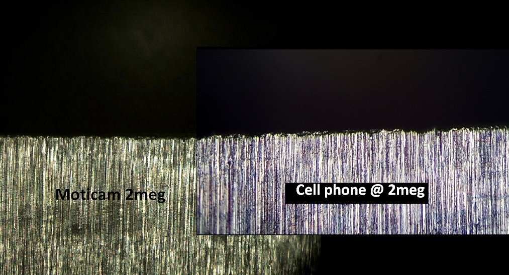
Here’s is a very close comparison of the exact same place on the blade. Again keep in mind the cell phone was only shot at 2meg, crippling its capabilities.
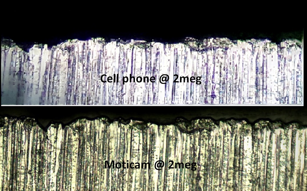
I know this may be hard to follow all of the above if your not the one doing it. The next post is the pay off….please see below.


Attachments:
You must be logged in to access attached files.
05/21/2016 at 4:52 am #34121So as I was shooting the last round of cell phone pictures I realized I was set at 2meg. I jumped it up to its maximum resolution(5312×2988) and took photos of the edge zoomed.
I also tried various light levels with different stacks but heres the final comparison I’ll be needing to do and I think you can see why….
Moticam @ x400 zoomed in photo editing to compare to cell phone below:
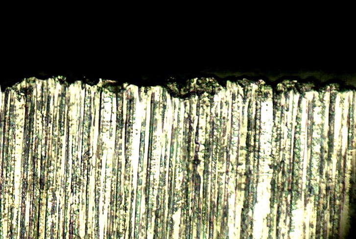
And Cell phone also @ x400 but also digitally zoomed x8. I did adjust the contrast on both final images but the difference is clear.
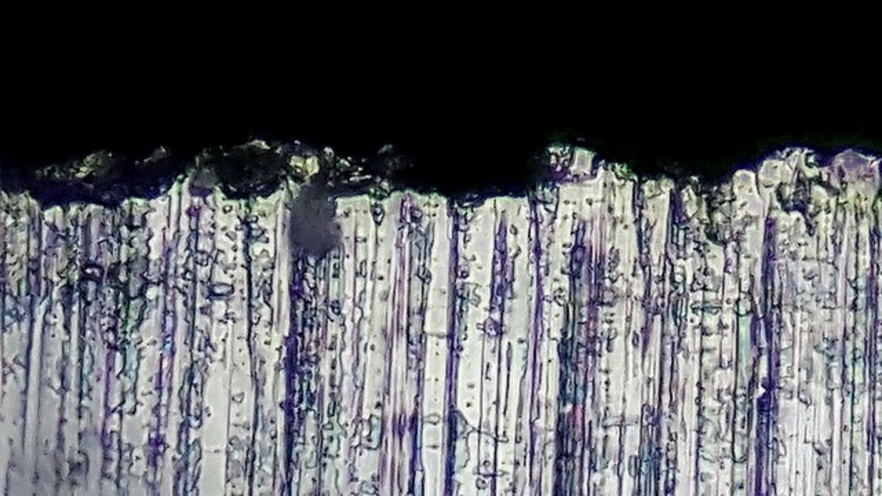
My buddy has a Nikkon SLR camera and I plan to pursue, but for now Im feeling good that the images are decent enough to move forward into actual testing of sharpening techniques.

Attachments:
You must be logged in to access attached files.
1 user thanked author for this post.
05/21/2016 at 3:25 pm #34133Good stuff Cliff! So, which camera are you going with? I watched the microscope videos and learned a lot, thanks for sharing them (Here) A little “dry” but very good info.
And just for grins, because MirrorEdge showed us close-ups of the diamond stones and you showed us the 220 teeth, how about a picture of what the steel dust looks like at magnification?
I have a new video on metal shavings and broken or fallen diamonds from one Wickededge sharpening session coming out tomorrow. My new set of stones are still being broken in. I am kind of suprised at the amount of diamonds in the dust? Maybe you will be too. I have also come to the conclusion that the Dino-lite USB SCOPES have a very wide field of view which helps with identification of objects. You see in the video. My next video will show both devices being used to observe the same collection of sharpening dust. Video is rendering now.
Eddie Kinlen
M1rror Edge Sharpening Service, LLC
+1(682)777-16221 user thanked author for this post.
05/21/2016 at 6:55 pm #34139Eddie for now its clear that the cell phone is taking better pictures at 16meg then the 2meg Moticam. Its is a bit more fiddly as I keep saying but mine also allows for hands free shooting with voice command. Makes it very easy to adjust the fine focus and say “shoot” repeatedly.
Also the Moticam doesnt have a zoom built in so you cant do things like this!
1 user thanked author for this post.
05/22/2016 at 2:24 am #34152Great stuff Cliff! The more I look and adjust my microscope the more I discover. I have ordered a micron calibration slide, because the Dino-light calibration target is not graduated small enough to properly measure and calibrate at these super high magnifications. Cliff is your scope “top lit”? Or, does it illuminate from under the stage? I see what your saying about the larger CCD sensor on the microscope camera compaired to a standard cell phone camera. I have a second biological microscope at home that has the larger format CCD camera, I’ll have to have my wife send that to me as well so I can see the differences. Dima had mentioned a adapter for a DSLR camera too. I’m kinda wondering what effect that would have too… Synergy Man you got me thinking now.
Sorry I haven’t been replying to all the good questions and also for the possibly excessively long posts. Ive really been in the flow after kids go to bed and end up dumping all my data here at 1am. Ill try to be more brief, lol good luck!
Eddie the calibration slide is an amazing item. How they placed the tiny little lines on there is another mystery. Increments on mine are .01mm, that may be an industry standard or some such thing.
The Scope is a true metallurgical and is lit from a unit in the upper rear that travels its own path and then shines down through the objective onto the subject.
Lastly when I talked with Motic of image sensor size vs. pixels he was rather vague. The one thing he did say clearly that CCD was much better then the older CMOS type….he then tried to sell me a $1000 camera as an upgrade. Haha
Im really curious to hear what ya’all think of the video from the last post just above? Next time Im gonna try to get it smoother, slower, and start close in and zoom back out. That was done by my fingers pinch zooming the screen while recording btw. Cheers!
05/22/2016 at 3:46 am #34154Very impressive, Cliff! I love the video too. It would be great if you could somehow plot in the scale. .01 mm is 10 micron, by the way, pretty small
 .
.Thanks for your reference to Kohler illumination, also because it made me Google this. Practice indeed seems more simple than the theory
 . I can now place Eddies ideas about light diffusion better as well. I can’t wait to try light diffusion on my incoming scope. Do you know if Kohler illumination is a distinguishing factor between metallurgical microscopes and “normal” ones? (And what could be other distinguishing factors?)
Molecule Polishing: my blog about sharpening with the Wicked Edge
05/22/2016 at 4:10 am #34156Mark the Kohler illumination technique I think is just a basic tool for all microscopy. I just finished image processing a full round of images from today, 280 images in total for 30 some image stacks. I did a 600 grit comparison of edge trailing vs. edge leading for a nice warm up and will post next.
I really need feedback on the forum as well on which images are pleasing to look at regarding brightness level etc. Overall I keep seeing improvements with each session.All pictures needed additional light level adjustments but Im learning important things I’ll share over in Eddies post about stacking and the Helicon software and questions I still have myself.
I was telling my wife tonight(she very interested in this stuff *eye roll*) that I know “how” to sharpen, but it’s all from word of mouth and feel….This is the “why” and to be able to finally see it has scratched my itch most excellently. You are gonna have some fun
2 users thanked author for this post.
05/22/2016 at 4:39 am #34161Great video idea Cliff , I LOVE IT! Here is the video on the sharpening dust. Keep in mind that this is from the first sharpening of “virgin” WickedEdge stones. No geometric shapes or interesting consistent patterns sorry…. Gib Curry, but lots of shards of different shapes and sizes. Many of the ribbons observed may be leftover from burrs or what is commonly called a wire edge. Many of the shards appear to be as thin to the diamonds in the photo as aluminum foil is to us in the “real world”. The metal is standard 440 carbon steel from a cheap Japanese “Dollar store” knife. I am surprised at how many diamonds I see. I expected to see a few but not the ratio seen in these images. Many of the diamonds appear to be fractured and few are whole diamonds stripped from the nickel plate.. I am going to do this after every sharpening until I get a clean edge (The break in period). The resulting edge was, as expected, very rough (Toothy) as the WickedEdge directions indicate it would be. Even though I spent some time on the blade all they way through both sets of ceramics. The edge was just barely shaving sharp when complete. I expect this to improve with each session but shows how important the “break in” period is. These diamonds are most certainly being “broken in” and off…. no exaggeration in that statement. The 50 and 80 grit diamond stones are noticeably smoother than before I started grinding. The cheap knife was originally ground as a chisel edge and now it is a standard double bevel “V”. I want to keep the “break in” as even as I can on both paddles for all the grits. The process took longer that It normally would because I was concentrating on making end to end passes with the stones.

Eddie Kinlen
M1rror Edge Sharpening Service, LLC
+1(682)777-16223 users thanked author for this post.
05/22/2016 at 5:19 am #34167Do you know if Kohler illumination is a distinguishing factor between metallurgical microscopes and “normal” ones? (And what could be other distinguishing factors?)
I’ll give it a shot to explain my understanding….
My Radical India metallurgical scope is using some other method of illumination called EPI Illumination (From One Side of the Object). It basically is a halogen bulb where the light from it goes through a heat sink and through a ring or Condenser Aperture “Iris like” diaphragm and then I have the ability to place filters and close the “Iris” diaphragm to adjust the light contrast and depth of field. The light bounces through the lens for top lit object illumination and then down to the object and then the reflection is driven back through the lens. On this microscope external light seems to have little or no effect on the object observed through the scope (By design I think). I was able to remove the halogen bulb housing and placed a high lumen LED flash light in its place with some effect .
“Normal” biological microscopes usually shine light from under the stage through the subject that is normally translucent to transparent and then the light goes to the objective lens. This allows operators to see the details in living multi cellular and single cellular organisms like plants and other biological subjects (Blood, Skin Cells, Plant Cells, liquids etc.).
As our objects are opaque and solid and can’t pass visible light through them, we must illuminate the subject from above or below to produce a reflection clear enough to view through the objective lenses much like a standard camera.
This is another case for subject awareness. Each microscope designed has a different purpose. For the study of rocks, we need the reflective variety used in physical sciences and the study of geology and in our case metal (Metallurgy). You can’t use a biological microscope without cutting the subject into small slices where light can pass through. Some gemstones can be seen with a biological microscope, however, cutting them thin enough to see them well is difficult with out fracturing the crystalline structure of the gem stone. It’s easier to just look from above. Some of the advanced microscopes are now inverted to allow the object to be viewed from below while the rock sits on top of the stage, however, the concept of reflection of light instead of transmission of light through the subject is still the goal.

This isn’t all the cases, for just about every application you could find a purpose driven microscope.
Eddie Kinlen
M1rror Edge Sharpening Service, LLC
+1(682)777-1622Attachments:
You must be logged in to access attached files.
1 user thanked author for this post.
05/22/2016 at 5:37 am #34169My metallurgical scope is using some other method of illumination called EPI Illumination.
That’s exactly the same setup I have on mine! So glad you mentioned it because I had no clue and the manual is more of a quick reference guide. The only thing my manual mentioned was to keep the 2 levers at the same level but I find Im getting better contrast with the condenser one(I think) a bit lower….there’s really not that much adjustment.
The real adjustment I have found so far is in the angle of the knife and being able to rotate the handle and secure it again firmly, observe the image, rotate & repeat until its where it captures well. Today used a small C-clamp to mount a tormek small knife adapter to the side of the table. Not perfect yet, but it works…lol.
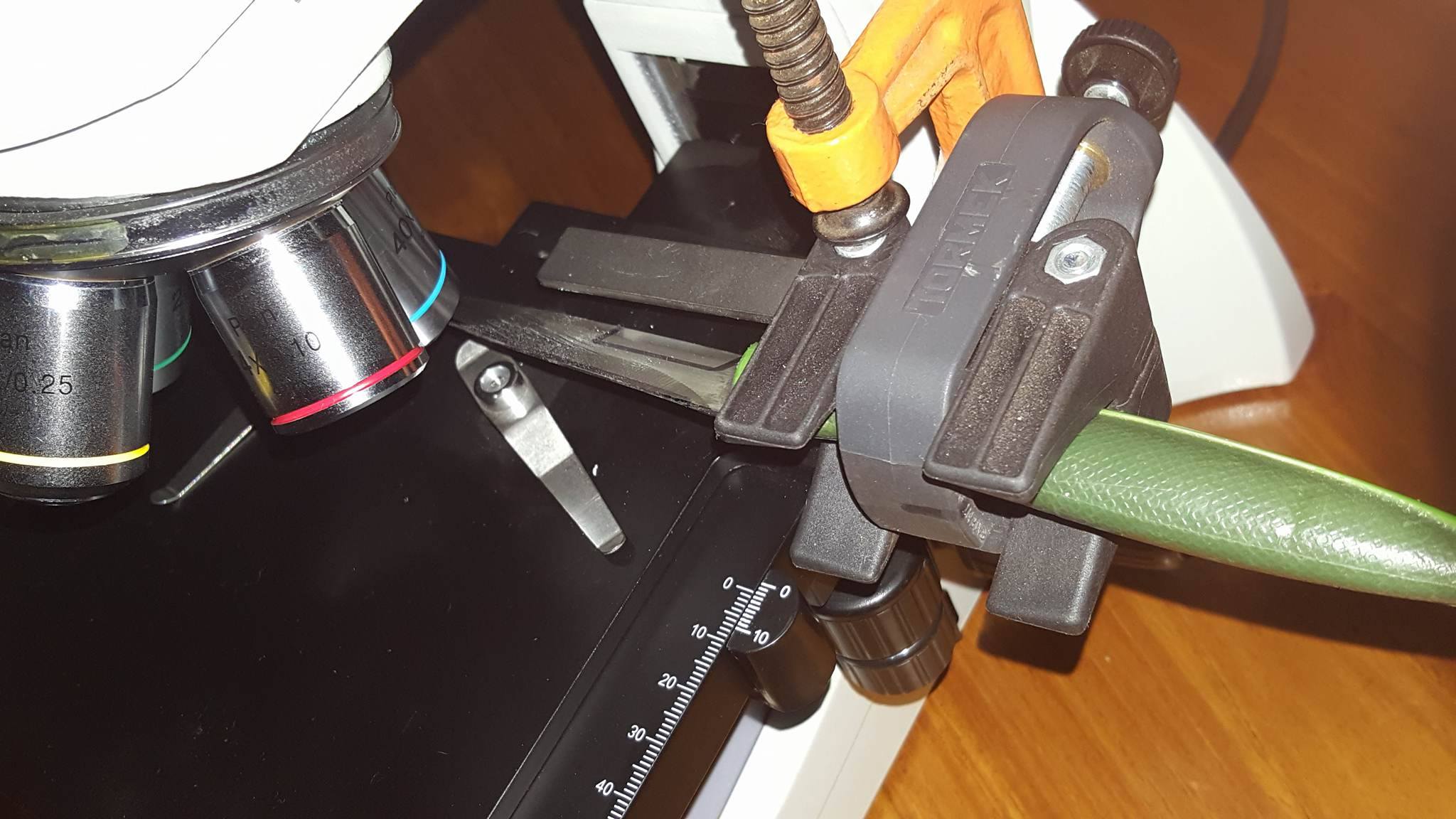
Attachments:
You must be logged in to access attached files.
-
AuthorPosts
- You must be logged in to reply to this topic.


