Blade alignment in the clamp: sweet spot & constant bevel angle/width
Recent › Forums › Main Forum › Techniques and Sharpening Strategies › Advanced Techniques and Sharpening Strategies › Blade alignment in the clamp: sweet spot & constant bevel angle/width
Tagged: Sweet Spot Theory
- This topic has 89 replies, 11 voices, and was last updated 01/11/2018 at 12:42 pm by
graphite.
-
AuthorPosts
-
12/28/2017 at 9:19 pm #44228
I use the depth key all the time (either top or bottom holes) because it holds the AG in place (although it tips a bit). I always place the tip in the center of a square so I just note J7 in my log. How do you hold the AG, the knife and tighten the clamp without having 3 hands – LOL
BTW, where do you live ? I am in NJ.
1 user thanked author for this post.
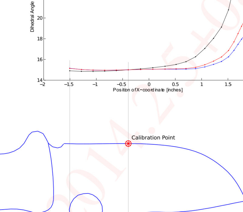
12/28/2017 at 9:20 pm #44229I kinda feel like the Spyderco LionSpy reinforces my point. Here’s a zoomed view, and note the scale is much coarser than the chef’s knife. On the straight part of the blade (and keep in mind this is a small knife) the angle deviation gets progressively greater than zero (relative to 15* target) as you get father away from the circle centerpoint that aligns with the curved part of the knife. I’d call it about .2 or .3 degrees of deviation just over about 3/4 of an inch on the straight part of the knife. It should be zero.
1 user thanked author for this post.
12/28/2017 at 9:38 pm #44230I don’t want to sound pompous (I’m really not), but looking through tons and tons of stuff over time on YouTube etc, there is SO much variance between people’s hand placements between their stroke, individual strokes, stroke differences between arms, likely stone thicknesses, wear on the stones, how many people aren’t properly setting the arms correctly to begin with, slop in earlier arms/stones, not using the micro adjusters, not checking between stones, inherent centering issue with 100/120 that 0.3 degrees is probably way more accurate than the average person is getting.
I really think it’s an exercise in academics at that point. The best way to confirm our individual suspicions would be to file, then profile a knife, (I did this on a clever as it was as straight and consistent as I could find) and measure the bevel with a microscope that is accurately calibrated. Compare against the model. I plan to do this. But again, I am doing 4″ folders, a different world to you guys with 10″ thin Chef’s knives. (My 130 didn’t fit a single knife I have, needed to order the 1/4″ jaws) Good luck supporting that by hand well enough to get it to 0.3 degrees even without painstaking effort.
Personally, I used to obsess over setting bevels correctly, measuring them, filing edges down etc to set the profile correctly. But what I found was doing it or not, I could easily get a great polish and HHT-0, the only difference is how much metal I “wasted” by filing it off instead of letting it get used for cutting and how it looked it you carefully compared both sides, and most people didn’t even notice I was doing it to their knives.
So the vast majority of what I do now is a kind of slow evolution. Move the knife ever so slightly towards a perfectly matched bevel, as best my eye can see, and I can measure with my Dual-Axis digital protractor. And it turns out, many production level knives do not even have matching secondary bevels. Welll, what the hell is the point of obsessing over 0.1 on the primary then?
Edit:
Oh also, I have also found a TON of knives do not have the apex in line with the center line of the blade. As in if you were looking at a cross section of the blade, and drew a line perfectly down the center from the spine to edge, the apex wouldn’t fall on that line. Add in variances in secondary bevel etc… Now if you are using the sharpie method like so many people do, you are not addressing that. I would bet not even with in a single degree. So the model assumes a starting point most people won’t even have. Accuracy beyond what lots of people seem to consider and people are still getting great results.
3 users thanked author for this post.
12/28/2017 at 9:51 pm #44231I get ya but I think you might be splitting hairs. When I put my straight edge against the edge at large zoom the segment from -.75 to -1.5 actually has a slight upward curve on the order of 1/16″ which is why the red curve goes up vs. downward curve on the previous chef knife with the red curve going down. I am sure Anthony must have run his simulation against a perfect straight line as part of proving the simulation out
The PIA with all this curve matching stuff is that “none” of my kitchen knives have curves which match the stock cone curves (over the full knife curve) within 3/16″. Variable angle control while traversing the full edge is my ultimate goal. What did you think about my dumb idea of twisting the knife clamp around the z-axis. (major mod)
1 user thanked author for this post.
12/28/2017 at 10:26 pm #44233Justin,
I hear you loud and clear and am surprised I haven’t heard from the regulars here that “sharp is sharp” and good enough to cut anything, etc. However, based on the simulations (which I have physically verified), longish 6, 8, 10 inch kitchen knives especially those which flex and cost $200+ per deserve the best I can do. I know it sounds silly but they will be in my will – LOL. Its like people fixating over the rims on their car or the watches they wear. I get pleasure form slicing a chicken like I am shaving. Wanna talk obsession — talk to the straight edge razor folks. BTW, I am on my 3rd IPA – LOL
Anyway, according to the simulations we are talking about possible 3-5 dps (6-10 deg included) variation over the length of the blade (worst case). Some blades (like chef) IMO are best with 20 dps by the heel for chopping and 15 dps at the tip for slicing but others are the opposite (like my steak knives which hit the plate all the time). The bottom line is that if we know what the trade offs are to get what we want and we have a method to get there then my knives will be much happier. Its a happy hobby for an engineer.
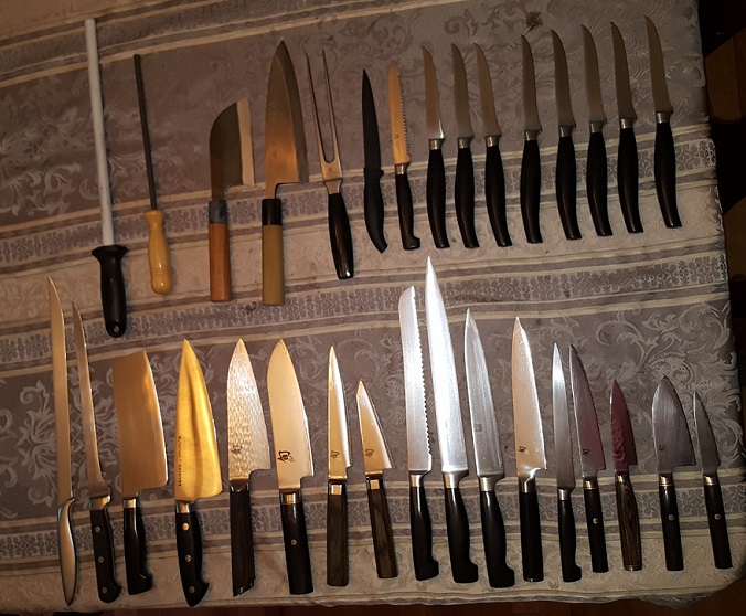
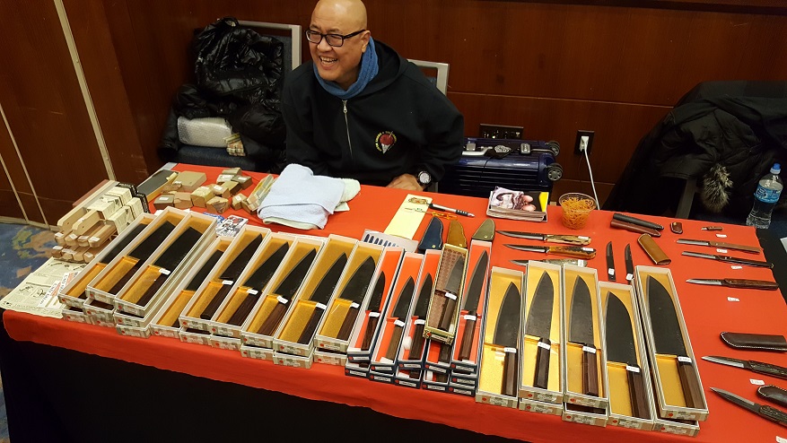
A couple of pics for context, my knives and a guy who flew in from Japan for the Jersey City, NJ knife show in November.
Attachments:
You must be logged in to access attached files.
2 users thanked author for this post.
12/29/2017 at 12:22 am #44238Readheads,
Don’t get me wrong, I am looking for a microscope, some I’m pondering in the $850-$1250 range to be able to do a better job at sharpening. I totally understand where you are coming from, the folders I have are all high end.
I was more speaking to getting too theoretical about a tiny difference that may or may not be present in reality based on a possible error in an model/algorithm, that very likely cannot be verified by us anyways.
Back in the day, they would call this Analysis Paralysis.
2 users thanked author for this post.
12/29/2017 at 7:32 am #44241I’ll try one more idea. See if you buy this:
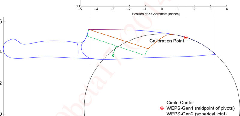
In dark orange, I drew a funky hypothetical blade shape on the back 70% of the chef’s knife edge, in hopes of making my point clearer. It curves down off the ideal circle and then has a break point and then a perfectly straight portion labeled as X (green text), out to the heel. I don’t know what you’d use such a blade shape for, but that’s not the point.
According to the “law of straight blades” the entire length of X should have zero angular error. It should be a perfectly horizontal line in the error plot of the x-coordinate (along the length of the blade) versus sharpened angle.
The way I’m interpreting his simulation, I don’t think it would be. His simulation is relative to the calibration radius, so you’ll notice the straight part of the dark orange blade edge labeled as X, crosses through the calibration circle. In his simulation, at that one point on the straight part X where the orange line crosses the circle, I think the angle would be the calibration angle. But for the portion of x that is inside the calibration circle, I think the simulation would show a progressively increasing angular error, and for the portion of x that is outside the calibration circle I think the simulation would show progressively decreasing angular error. But (according to section 5) there should be zero angular error for the full length of x.
The sharpened angle (theta) is calculated as the arctan of h/d (pg 66). But h is a fixed value because the pivot point (center of the circle) is fixed for this simulation run, while d varies over the entire length of the new straight part X. Because of that, it CAN’T be a constant angular value (it will have a different angle for every point along X). But section 5 says X should be a constant angle. This is the contradiction I’m seeing/imagining between section 5 and section 6 of the paper.
Anyway, as Justin notes, we aren’t going to be able to resolve this. But I’d like to know if there’s something fundamentally wrong with the way I’m looking at this in concluding there’s a contradiction between the analysis in section 5 and section 6 of the paper.
12/29/2017 at 7:43 am #44242Redheads, nice knife collection!
re: “What did you think about my dumb idea of twisting the knife clamp around the z-axis. (major mod)”
I’m not sure I understand what that twisting of the clamp would do. It seems like you’d want to maintain the plane that bisects the centerline of the knife blade and just vary the x-y position (either of the knife in the clamp, or the pivot point). Is your thinking that, mathematically, twisting the clamp about its centerline would achieve the same end as varying x-y with the clamp in a fixed plane?
1 user thanked author for this post.
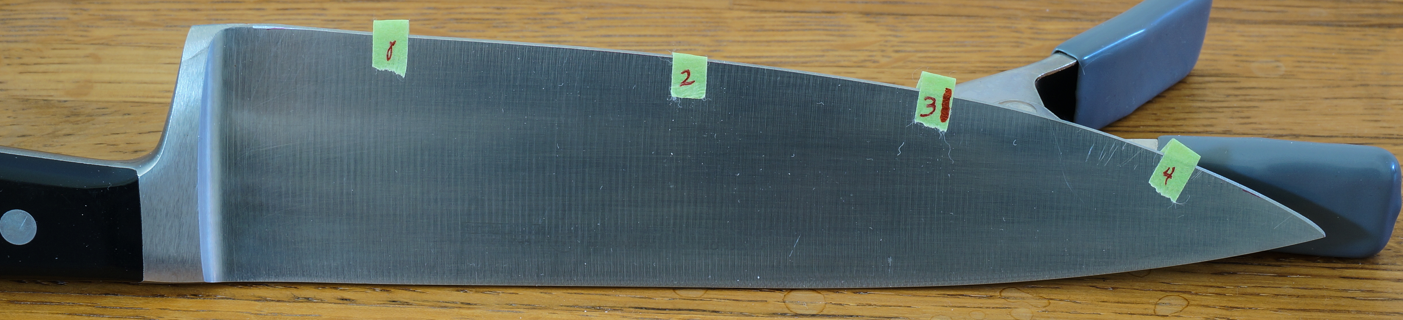
12/29/2017 at 10:57 am #44246RESULTS OF SHARPENING A WUSTHOF CHEF’S KNIFE USING THE CIRCLE CONTOUR JIG
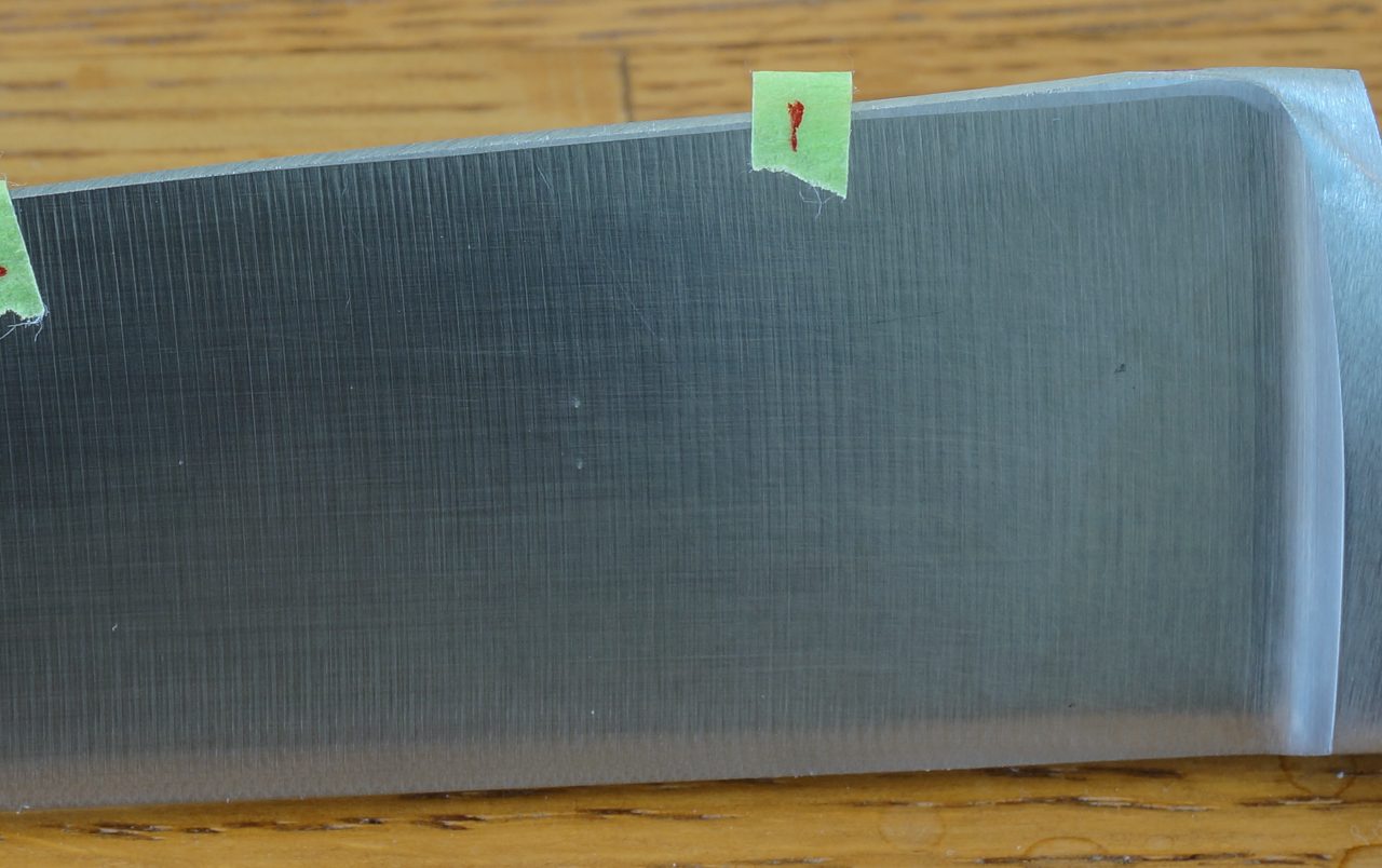
This is using the jig with the revised minimum circle radius of 6-1/8 inches. This knife is about 30 years old, and I had previously sharpened it on an Edge Pro (where I messed up the bevel near the heel on one side, as the pics will show), and maintained it on a ceramic rod.
I picked this knife because it had reasonably good alignment to one of the circles, compared to my other larger knives. I first found the straight-to-curved breakpoint on the knife using the process I described previously (the straight part is the part of the knife where the mild curve doesn’t stray more than 1/16 inch from being perfectly straight). I marked this breakpoint on the knife (the red mark on the green tape), and proceeded to try and find a circle on the jig which aligned with the curve of the blade to the right of the red mark. This turned out to be “contour L” (note that it aligns with an undrawn contour that is parallel to contour L but about 2/3 of the way to contour M. The rest of the knife (under the assumption that it is relatively straight to the left of the red mark) was not considered in the alignment process. I got better alignment with the contours by using the upper depth key holes, and I shifted and tilted the knife (maintaining contact with one prong of the depth key) to get the best match to a contour (or in this case an undrawn contour between the drawn ones).

This knife had some existing faceting due to my mediocre skills with my old Edge Pro and manually holding the blade stable during sharpening, so I started at 100 grit, and went to 200, 400, and stopped at 600. It took a fair bit of grinding at 100 grit to get rid of the faceting.
Below are some photos after sharpening.
Here’s the left side. The bevel was pretty consistent to the naked eye, but (probably due to operator error) a bit wider at the tip, from tape mark 4 to the tip.
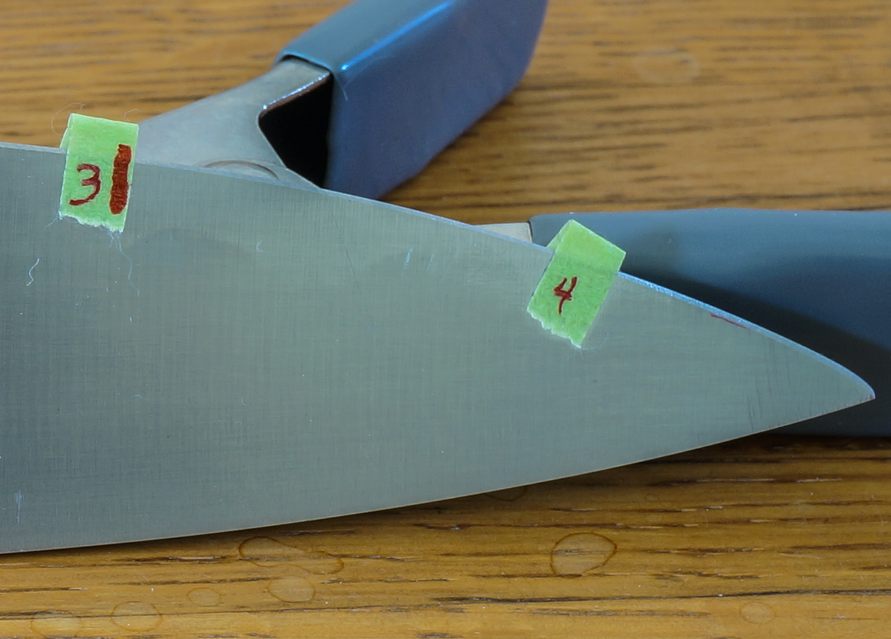
The bevel between mark 3 and 4 is a bit hard to see against the similar color background so here’s a zoom of that area
Right side: continuted on next post (wouldn’t allow me to add it here)
3 users thanked author for this post.
12/29/2017 at 10:58 am #44247Relative to the dark orange above: I do not know, I started to go back to Anthony’s document and my brain started hurting again. The only thing I can think of is that Ch. 5 focuses on WEPS Gen-1 (non-spherical) and the simulations focus on Gen-2 (spherical), maybe that has something to do with it.
1 user thanked author for this post.
12/29/2017 at 11:00 am #44248Here’s the right side. Note that the area on the edge between the heel and about midway between tape marks 1 and 2 is where I missed the bevel previously using the Edge Pro.

…and on closer examination you can see the old/missed bevel but the newly ground bevel was pretty consistent with the rest of the knife.
Under magnified view there is certainly some measurable difference in the bevel widths, and for whatever reason, the bevel on one side is wider than the other (which I also assume is operator error). I guess this must just be a matter of different stone pressure on my dominant hand versus my non-dominant hand, or maybe I’m bad at counting to try and use the same number of strokes per side.
So this sample of one knife at least shows some promise that a circle contour jig (in the hands of someone with more WE skill that I have) could be a valuable tool for aligning a knife in the clamp, easily and safely.
2 users thanked author for this post.
12/29/2017 at 11:09 am #44249Nice pics, can you take some angle measurements along the edge (using angle cube on both sides while mounted in clamp), maybe every half inch or so and then graph the data ? I think the curve would be similar to the simulation. Remember to keep the angle cube plumb.
Also, the bevel width is also a function of the blade thickness.
12/29/2017 at 11:10 am #44250graphite, I don’t think there is anything fundamentally wrong with how you are interpreting the model.
I have watched the video of the Chef’s knife, and paused it, moving it backward and forward to see how all the lines and different calibration points change and been slightly skeptical of the heel section myself, as my knives often end up a lot more tip down than the constant horizontal orientation he depicts, and noted my heels are never that far out, but also thought it could be due to his constant horizontal mounting. Or just bigger knives.
I also find the very end of the heel to be generally a tough spot to get right, in particular when there is no sharpening choil present. So sometimes I mount in a way that lets me get at the heel better, though at a slightly different position than ideal for geometry because the ugly spot on the heel I can’t get will bug me more than a slight difference in the angle on the edge. Additionally, when you get into various techniques to prevent micro chipping of steel, to align the teeth with the way you intend to cut with the knife, to intentionally maintain or create a differential geometry (I often do this as I prefer different parts of the edge for different tasks) your mounting will look nothing like his, and so it all goes out the window anyways.
I felt it was useful to explain in principle how the geometry of the sharpener works, but haven’t found it any form of instruction.
1 user thanked author for this post.
12/29/2017 at 11:20 am #44251Great pics, and glad to see you put a knife through the paces.
Question for you, do you plan to measure your bevels and compare against the model now? I wonder what level of accuracy you will reach compared to your expectation!
Keep in mind, while you mention operator error, part of the charm of this system is it takes a lot of that out. That being said, you can see how results still vary greatly, well past the .3 degrees mentioned earlier despite using a jig that is well more advanced than the sharpie method.
The next step to check your work would be to file the edge down, medium bastard file will do it quick, take some measurements with a caliper and profile it yourself.
Have any microscope pics of the apex or edge? Would love to see how that ‘scope of yours is doing before I pull the trigger.
1 user thanked author for this post.
12/29/2017 at 1:15 pm #44252The first is the lack of a wide clamp to minimize flex in thin knives. It should be a piece of cake to modify the CAD drawing and get them made.
@Readheads – we’re working on that.
-Clay
4 users thanked author for this post.
-
AuthorPosts
- You must be logged in to reply to this topic.