Blade alignment in the clamp: sweet spot & constant bevel angle/width
Recent › Forums › Main Forum › Techniques and Sharpening Strategies › Advanced Techniques and Sharpening Strategies › Blade alignment in the clamp: sweet spot & constant bevel angle/width
Tagged: Sweet Spot Theory
- This topic has 89 replies, 11 voices, and was last updated 01/11/2018 at 12:42 pm by
graphite.
-
AuthorPosts
-
12/26/2017 at 5:16 pm #44179
@MarcH @graphite I’ve fixed the issue where the earlier replies were stuck at the bottom, as if they were always the newest. The explanation is kind of technical, and I’m not yet sure exactly how it happened. In short, each reply to a topic receives an ID, as well as an optional reference to another reply. If a reply doesn’t refer to a previous reply, i.e. it’s just a new reply in the topic, then it’s given a reference of 0. For some reason, the two replies that were stuck had been set as referring to themselves, rather than another reply, or no reply. I don’t know if this happened as a result of moving the topic to another forum, but it seems like that somehow caused it. Thanks for the heads up, and I’ll keep an eye out for any other strangeness.
Working to make knife.wickededgeusa.com a great forum!
1 user thanked author for this post.
12/27/2017 at 9:44 am #44184Marc, was I able to address your question re: the angle bar setting not being a factor for the circle contours, or if not, please make any additional points you don’t feel are addressed.
Maybe another way to look at it is that the blade profile (outline) is matched to the circles on the jig, not the bevel. The sharpening angle can be anything (within reason) for that given blade profile and it will hold that sharpening angle constant so long as the blade profile is matched to the circle arcs. The angle setting is done independently of setting the position of the knife in the vise to match the circle contours. You could set the sharpening angle either before or after you align the blade in the clamp to match a circle contour.
And anyone else, please feel free to chime in with your views.
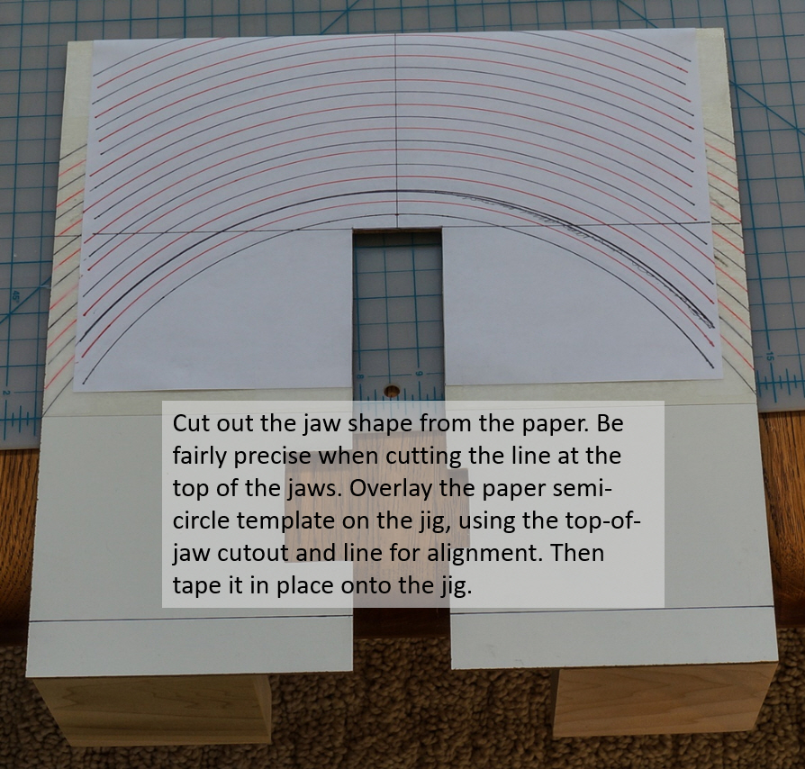
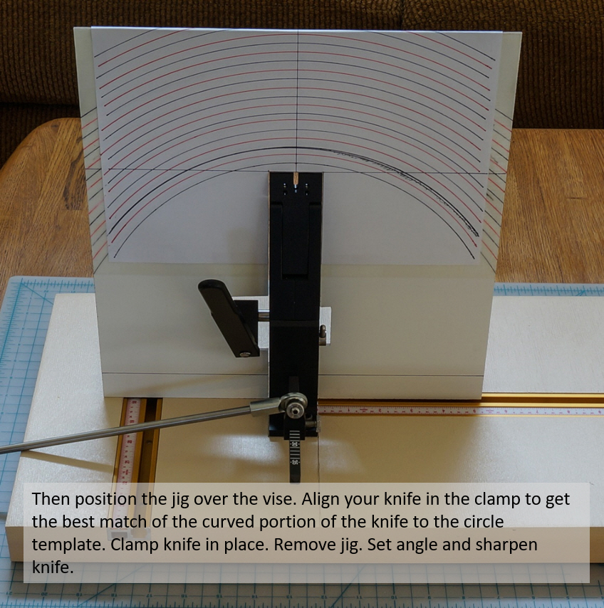
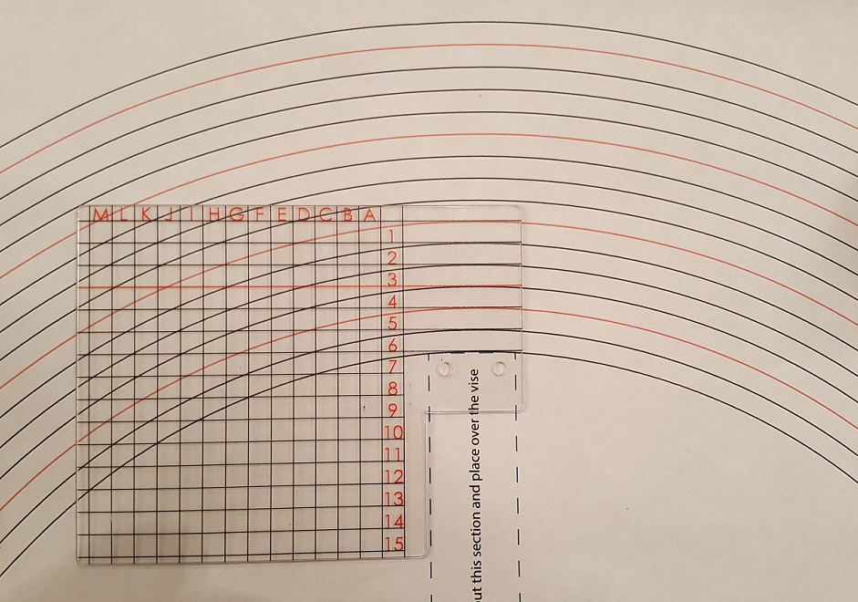
12/27/2017 at 12:35 pm #44186How to draw a semi-circle template for a GEN3-2017 vise, to overlay onto a circle contour jig:


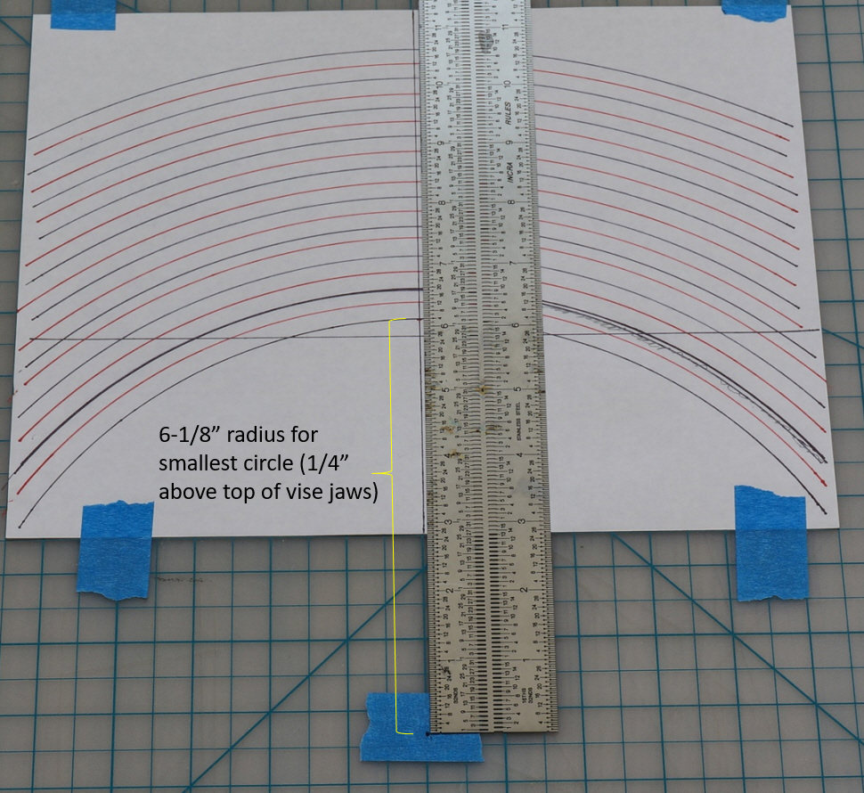
Of course, nobody should actually sharpen a knife based on this until someone with some WE experience and credibility has given their OK. I’m just describing the process for creating the circle template based on the latest info on where the centerpoint of the smallest circle should be and its radius for a GEN3-2017 clamp.
If you ever had a need to change the circle radius (for example, you installed a riser block, or used a different clamp, or used the low angle adaptor) you’d just follow this same process of generating a new sheet with circles having different minimum radius, and overlay it onto the jig.
12/27/2017 at 4:20 pm #44188I can’t locate it, but several years ago, maybe 2013 there was a long discussion over this concept. It was on a YouTube video, someone made the concentric circles on cardboard. I can picture it clearly, but can’t find it.
Anyways, what most of us found at the time is that getting the tip in a spot perfect for it left the heel too far out, so 2 position sharpening became the way to go about it on larger knives.
Not sure that is useful info.
12/28/2017 at 8:48 am #44198Justin, that sounds like the video that revived this discussion in the first place.
There are certainly limits on what a spherical ball joint sharpener can be expected to do at a single clamp point (and Anthony Yan’s paper covers those limits), but there must also be a pretty high percentage of knives where the user can get satisfactory to excellent results without having to re-clamp the knife in a second position (or these sharpeners would not be so popular).
This is where understanding the theory at some level would help the user to gauge their expectations for a given knife shape, and the circle contour jig, it seems to me, gives you a visual indication of how close you can get to the geometry that a spherical ball joint sharpener is ideal for, before you swipe any abrasives across the edge.
If you have a knife with a lot of curve in the belly then this type of sharpener (used at a single clamp position) is going to result in some sharpening angle variation no matter how you align the tip portion. That may or may not be acceptable to the user. But it’s also not the case that any arbitrary curve at the tip end will sharpen perfectly. The jig’s circles have to be based on the correct center point and the knife has to be positioned correctly to minimize the angle error, and the circle jig is one way the user could do that easily and safely.
Every knife with a curved tip is not going to match up perfectly with a circle contour. There are just too many different knife shapes. But it still brings me back to the original point for this jig, which is, why go through trial and error positioning of the knife when there is a template you can put on the jig as you clamp, and in a matter of seconds you can say, this is about as good a position as I can get, and clamp it down and get on with the sharpening.
It almost seems like some of you guys are viewing this jig concept as an alleged miracle cure for setting the knife position to get perfect results every time. It’s not. It simply allows the user to visually MINIMIZE the sharpening angle error due to the position of a given knife in the clamp, and to do it quickly and safely.
At the end of the day, the shape of the knife sets what can be achieved, and the sharpener has to work within that. For some knives you can only get moderately close to what a spherical ball joint sharpener is capable of, and for others you won’t get very close at all unless you re-position the knife multiple times. But why guess when you can get an indication before you swipe your first stone, at whether you’re close to what the theory says the sharpener is capable of doing.
12/28/2017 at 4:28 pm #44205Every time someone goes over something that has been discussed before, there is the chance that they will find another perspective and bring something that had been previously overlooked. So I’m happy to see it revisited.
Personally, I haven’t experimented with the circle jig much (I made a cardboard one for my old system a long time ago), as almost all my knives are quite short (3″-5″), folders mostly, but I understand how someone doing primarily kitchen knives would be way more aggressive with the pursuit of something better than trial and error. I’ve never done a 2 clamp point knife myself.
I think the jig is a good idea, and a great visual representation of Anthony Yan’s paper. It’s certainly better than what I do, which is eyeball my knife with my finger in a pointing position on the arm. I have several knives that all have the same blade, and a few more with the same profile just a slight size difference so I usually make 1-2 small adjustments to my position and off I go.
When I do other people’s knives, I always try to leave as much steel on the knife as possible, and they are usually more acute near the tip so I follow that, or make small corrections each session so I don’t even bother recording the position anymore (I might never see that particular knife again).
Setup is a big time consumer for sure, so if there is a way to improve it, I am in. I think I will overlay a few lines on the back of my alignment guide, or use a sliding washer as a reference on my arm at some point (finger isn’t ideal), but if you come up with something commercial, I will buy it!
I say finger isn’t ideal, as after years of doing things a certain way and never getting cut, I cut myself really really good on Christmas. Sooooo I’ll be wearing a pair of cut resistant Ansell HyFlex gloves from now on.
12/28/2017 at 5:54 pm #44212… getting the tip in a spot perfect for it left the heel too far out.
Justin and all, there’s a contradiction in the results in Anthony Yan’s paper between section 5 and section 6, and you have to read between the lines and try to understand what the limitations on his circular blade simulations are, in order to resolve the contradiction.
In section 5 (in particular section 5.3, pg 53) he concludes that for a straight blade, a WE with a spherical ball pivot would perfectly sharpen a constant angle the full length of that blade, no matter how far away from the center of the blade you sharpen, and no matter what angle the straight edge is tilted at in the vise. Numerous threads here and on other forums had the same finding regarding straight blades, so let’s consider this an undisputed fact.
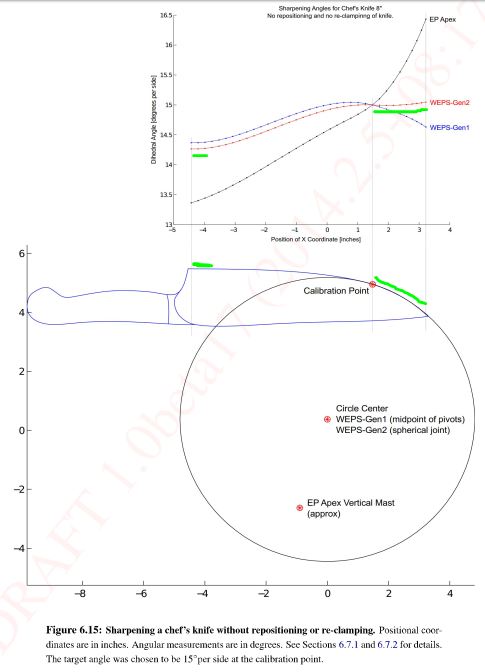
Meanwhile, in section 6 for the chef’s knife example, he shows (figure 6.15) that he can sharpen the circular front of the blade essentially perfectly (on the GEN2 w/ spherical joint), but the simulation results for the straight portion near the heel has a progressively larger angular error as you traverse the straight portion of the blade toward the heel. Note that at least a couple inches of that blade near the heel is perfectly straight, so this result contradicts his findings in section 5.
How can that be? Both these contradictory things can’t be true. Keep in mind that the straight portion of the blade doesn’t know whether the tip portion is curved, and vice versa.
I believe the reason for this contradiction is straightforward if you read how he did the simulations for the curved blade, and the limitations that would produce in the result. He modeled the entire blade relative to matching the curved tip to a circle centered at the spherical pivot point. So the straight portion was not interpreted by the simulation as a straight portion. He modeled the blade point-by-point so there was no way for it to detect that a part of the blade was straight. Every point along the straight blade was interpreted by the simulation as a deviation from the perfect circular match he had at the tip. On the straight part as you move toward the heel, the simulation interpreted it as a progressively larger radius (relative to the fixed radius that matched the tip perfectly), leading to the angle variation shown in the graph for the straight part of the blade.
So the issue is that the circular blade simulation uses circular geometry for the *entire blade*, when it really needs to switch to planar geometry once it’s on the straight part of the blade, in order to duplicate the undisputed results for straight blades from section 5.
That would have been pretty hard to code, but in any case, I think that’s what explains the contradiction between the results of section 5 for straight blades (which no one disputes), and the straight portion of curved blades in section 6. I think it’s also the case than nobody disputes the results for the curved part of curved blades in section 6.
To summarize, in the section 6 curved blade simulation, each point along the blade was analyzed for its deviation from the circle radius that matches the tip region of the knife. That means that each point along the *straight* part of the blade would be interpreted as an increasing radius (as you go toward the heel) from that ideal radius of the tip area. But it’s straight (or at least at some point it is straight for all intents and purposes all the way to the heel), so that’s not the correct geometric model to use for that part of the blade. Per the conclusions in section 5 it should sharpen at constant angle for the entire straight part because it’s the planar geometry of section 5 that applies there, not the circular geometry of section 6.
What do you think?
1 user thanked author for this post.
12/28/2017 at 6:18 pm #44214As a kitchen knife sharpener (only my own + friends), there a 2 things that bug me about WEPS. The first is the lack of a wide clamp to minimize flex in thin knives. It should be a piece of cake to modify the CAD drawing and get them made. The second is the angle “deviation” along non-straight, non-cone circle profiles. I have and will continue to live with the deviation issue because 3-5 dps deviation is livable and even useful if you want say a more acute tip and obtuse heel (or vice versa). But that doesn’t deter me from thinking up possible solutions. As pathetic as it sounds I have drifted off to sleep many times considering options – LOL !
Recently I was considering what a machine/robot would do. The knife or stone would need to move during each stroke as some function of the profile. While we can’t necessarily mod a WEPS realistically to do that, what if we incorporated a twist about the z-axis (vertical) ? It is also non-trivial but would be a great Sr Project for an Eng’g student. It wouldn’t have to twist much (it would be more like a z-axis bias).
Q: What would the twist do to the angle ?
1 user thanked author for this post.
12/28/2017 at 6:46 pm #44216Graphite,
I don’t see the contradiction. The 2 sections of the blade which have minimal deviation (<0.1 dps) are the tip (lined up with the cone circle) and the ~1 inch by the heel (straight), the rest of the knife is not straight and will have a deviation curve as a function of the profile. See markup in green below. I wish I could code up the algorithm based on a scaled picture of the profile. Then we would know exactly the deviation we are dealing with.
Attachments:
You must be logged in to access attached files.
1 user thanked author for this post.
12/28/2017 at 7:27 pm #44219But the blade is straight from at least -2 to the heel, and only a small deviation from straight beginning somewhere between 0 and -1. You’re drawing the green line to match the simulation output, not the knife. If you didn’t have that simulation output, knowing what you know about sharpening straight blades regardless of the tilt, where would you guess there should be no sharpening angle error?
If you chopped off the tip of that knife from about -2 to the tip, and applied the results of Section 5.3, it should sharpen a perfectly consistent angle, not a .3* variance. Now .3 isn’t that much, but it should be zero.
If Anthony were still around, there are several other knife profiles he could run that I think would make this clearer.
1 user thanked author for this post.
12/28/2017 at 8:01 pm #44220The segments you are calling straight are not “exactly” straight, they are ever so slightly curved. I put a straight edge against my 20 kitchen knives and very few of them have any exactly straight segments.
In Section 6.7.5, Anthony shows a knife with an exactly straight segment:
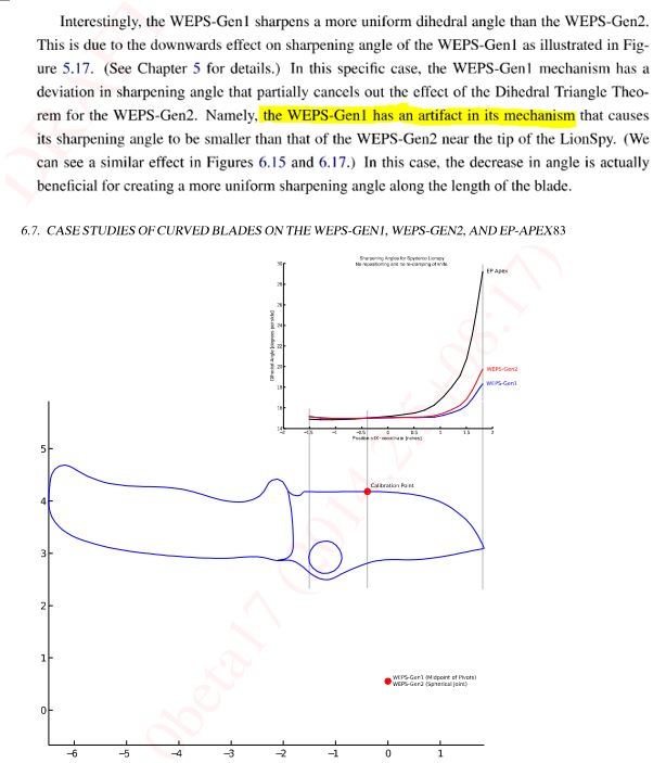
I also find it interesting that the yellow highlight brings up the “artifact” which made me start thinking about purposely changing the angle as you traversed the edge.
Attachments:
You must be logged in to access attached files.
1 user thanked author for this post.
12/28/2017 at 8:29 pm #44223I downloaded Clay’s circles and lined it up with the Alignment Guide (AG). Being that the AG is used to indicate the position of the tip and the majority of the time this is where the curve is, I think it makes sense to transcribe the curves to the AG. I always make sure the tip is in the AG for repeatability. Maybe the AG should be bigger to allow for more variation, I am not sure.
WDYT ?
Attachments:
You must be logged in to access attached files.
1 user thanked author for this post.
12/28/2017 at 8:40 pm #44225What if we inserted a 12″ long straight segment into that chef’s knife beginning at x= -4 (so the heel would now be at x= -16.5). Per the “law of straight blades sharpened on a spherical ball joint” the simulation result should show zero angle deviation (even if we tilted this straight segment at an angle). But if I’m understanding the way he set up his simulation based on each point on the blade relative to a circular geometry, it would not show zero deviation, it would show a progressively larger angular error as you went toward the heel because each point along this straight blade is farther and farther from the ideal radius for the curved part of this knife. Anyway, it’s just a hypothetical question for now.
In another thread I asked how much deviation from a straight line is too much (before the angle change is visible to the naked eye), and I speculated that if the peak of the curve in an edge does not stray more than 1/16″ from a straight line drawn between the endpoints of the curve, you probably cannot notice any sharpening angle deviation (compared to if it were perfectly straight). Do you have any views on that, or other appropriate “deviation from straightness” number?
I ask for a practical reason. Namely, if we can approximate most knives as 2 segments: a curved segment near the tip, and an “essentially straight” segment from there to the heel, it makes the blade placement in the clamp (along with a circle contour jig for the front curved part of the knife) more straightforward.
1 user thanked author for this post.
12/28/2017 at 8:52 pm #44226That’s a good idea to combine the AG and the curves (but maybe just the vertical lines if the curves are in there too?), and I’d agree that a bigger alignment guide might make sense. But you’d have to be sure the reference point for the curves lines up right.
Personally, the way I use the AG is I put the inside corner on the upper right corner of the vise (the tip end of the knife is to the right), since this lets the AG sit flatter onto the knife. But you have to make a relief cut with a rat tail file in the inside corner because the radius of the plastic corner is too small and it wobbles a bit without the relief cut. If the AG were a tad bit thicker it would be even easier to do it that way, and no fumbling with the depth key.
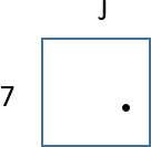
The way I log the position of the tip in my notes for a given knife is I just draw a square with the alphanumeric coordinates from the AG and put a dot where the tip is. Easier that trying to write it out in words.
1 user thanked author for this post.
12/28/2017 at 9:01 pm #44227This is pretty rough but it correlates (I think):
I zoomed in on Anthony’s chef knife on my computer and eyeballed a straight edge against two almost exactly straight segments:
Segment 1: from -3 to -1, 1/16″ deviation from straight, angle change of ~0.4 dps per the simulation prediction
Segment 2: from -4 to -2, 1/32″ deviation from straight, angle change of ~0.2 dps per the simulation prediction
I have seen this in real life although it is tough to completely verify because I have the stock single axis angle gauge; I am going to buy a dual axis so I don’t have to deal with plumbing a single axis (finger cut warning!)
Also, have you watched the movie simulation of the chef knife, if I remember correctly the angle can change upto ~4-5 dps depending upon mount location. To me that is unacceptable especially if the blade flexes which makes things even more uncertain. Don’t get me wrong, I love my WEPS but I do not think we get as much control out of it as we could.
Note: I just realized that this is deg per side (dps) so the included angle would change by twice the delta dps !
1 user thanked author for this post.
-
AuthorPosts
- You must be logged in to reply to this topic.