Blade alignment in the clamp: sweet spot & constant bevel angle/width
Recent › Forums › Main Forum › Techniques and Sharpening Strategies › Advanced Techniques and Sharpening Strategies › Blade alignment in the clamp: sweet spot & constant bevel angle/width
Tagged: Sweet Spot Theory
- This topic has 89 replies, 11 voices, and was last updated 01/11/2018 at 12:42 pm by
graphite.
-
AuthorPosts
-
12/21/2017 at 2:05 pm #43317
Clay, when I printed it out and cut an outline and overlaid my jig, the scale is off by quite a bit (the circle radius in the printed version is quite a lot smaller than on my jig):
2 users thanked author for this post.
12/21/2017 at 2:52 pm #43319No they’re circular (drawn with a compass using a common center point, so the lines had no choice but to be circular).
If you think about it, 7″ radius = 14″ diameter, so if you extend my smallest 7″ radius circle about 1″ on both sides of the white panel you can see that it would reach a semi-circle if it had been 14″ wide. In the printed version of your template, note that your smallest circle reaches a half-circle well under the width of the paper.
Actually, I just measured the printout and your smallest circle is 7″ diameter.
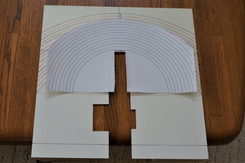
Edit: if I print your template pdf with a custom scale of 200% in landscape mode, the arcs match my jig, but then the cutout for the vise is too large.
Here’s a photo of 200% scaled overlaid on my jig:

3 users thanked author for this post.
12/21/2017 at 2:59 pm #43323Actually, I just measured the printout and your smallest circle is 7″ diameter.
That would explain it 🙂
-Clay
1 user thanked author for this post.
12/21/2017 at 3:39 pm #4335712/21/2017 at 3:52 pm #43370@graphite – now that I’m playing around with this, I’m wondering how you came up with a starting circle w/ radius of 7″ tangent to the top of the vise. Wouldn’t we be looking for a series of cones that have their centers at the pivot point of the guide rod and wouldn’t the cones change based on the angle at which the pivots are set?
-Clay
12/21/2017 at 4:09 pm #43371Clay, yes, the circles on your revised pdf line up (the cutout lines for the vise are too narrow, but that’s just a matter of cutting it bigger).
I think no matter where the pivot is located along the angle bar, it’s always bisecting the center of the vise, and it’s still tracing out circles in the plane of the blade’s edge no matter the location of the pivot on the angle bar. The radius that corresponds to the edge of the knife at the clamp centerline will vary depending on the angle bar setting, but since the circles are just an alignment reference and their specific location/radius doesn’t matter, my thinking is that this jig serves the same purpose regardless of the actual angle bar setting.
But I always reserve the right to get smarter and change my thinking ;o)
1 user thanked author for this post.
12/21/2017 at 4:17 pm #43380@graphite – I’m thinking of trying the following to continue testing your ideas:
- Set the guide rod at some angle
- maybe start at 20 degrees just to have some place to start
- Attach a blank piece of paper to the vise, on the opposite side from the guide rod that I’m testing
- Attach a pen to the guide rod such that it can scribe on the paper and is aligned with the top of the vise
- Complete that semicircle
- Move the pen up the guide rod 1/2″ and reattach, then scribe a new semicircle
- Repeat for a few iterations
-Clay
1 user thanked author for this post.
12/21/2017 at 5:26 pm #43564Clay, I did something similar to that before I built the jig. I traced out semi-circles as I held a sharpie in a constant position on the guide rod, and then at various offset, parallel semicircles when I moved the position of the sharpie on the rod. I used a piece of thin cardboard since the fixed length of the guide rods gets in the way if you use something too stiff like box cardboard. But it all makes sense when you think about the rod on a fixed pivot point and the tip of the sharpie at a fixed point on the rod. With those constraints, all it can do is trace out a circle on the plane that bisects the center of the blade edge. Still, it’s useful to see it with your own eyes.
Here’s a photo of that original cardboard test I did, including the outline of the vise jaws. You’ll have to forgive the jittery sharpie lines, since this setup with the cardboard and manually holding the sharpie on the rod was a bit flimsy.
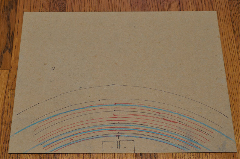
Ignore the blue lines. After I completed this exercise I took the cardboard and taped it down on a workbench, and then I got out my beam compass and put the blue colored pencil in it. I wanted to convince myself that these arcs I drew by sweeping the sharpener rod with the sharpie were in fact part of concentric circles. The beam compass traces in blue (with the pivot point perpendicular to the centerline of the jaw outline) confirmed it for me.
Let me know if you get a similar result with your tests.
12/22/2017 at 1:21 pm #4408312/22/2017 at 2:02 pm #44087Hi Clay, you must have been testing something different from what I was thinking. What are we looking at here, and more importantly, what conclusion did you reach?
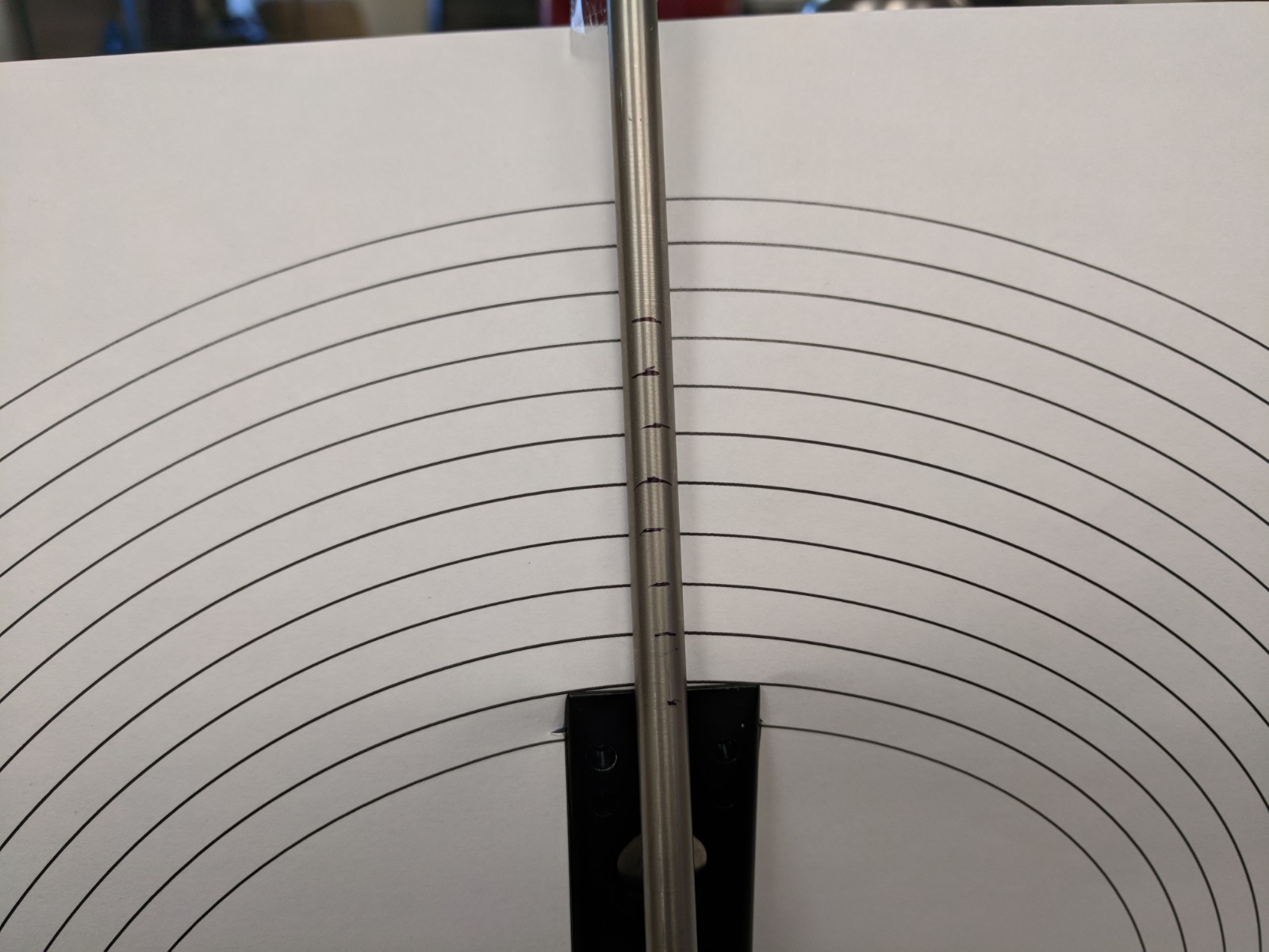
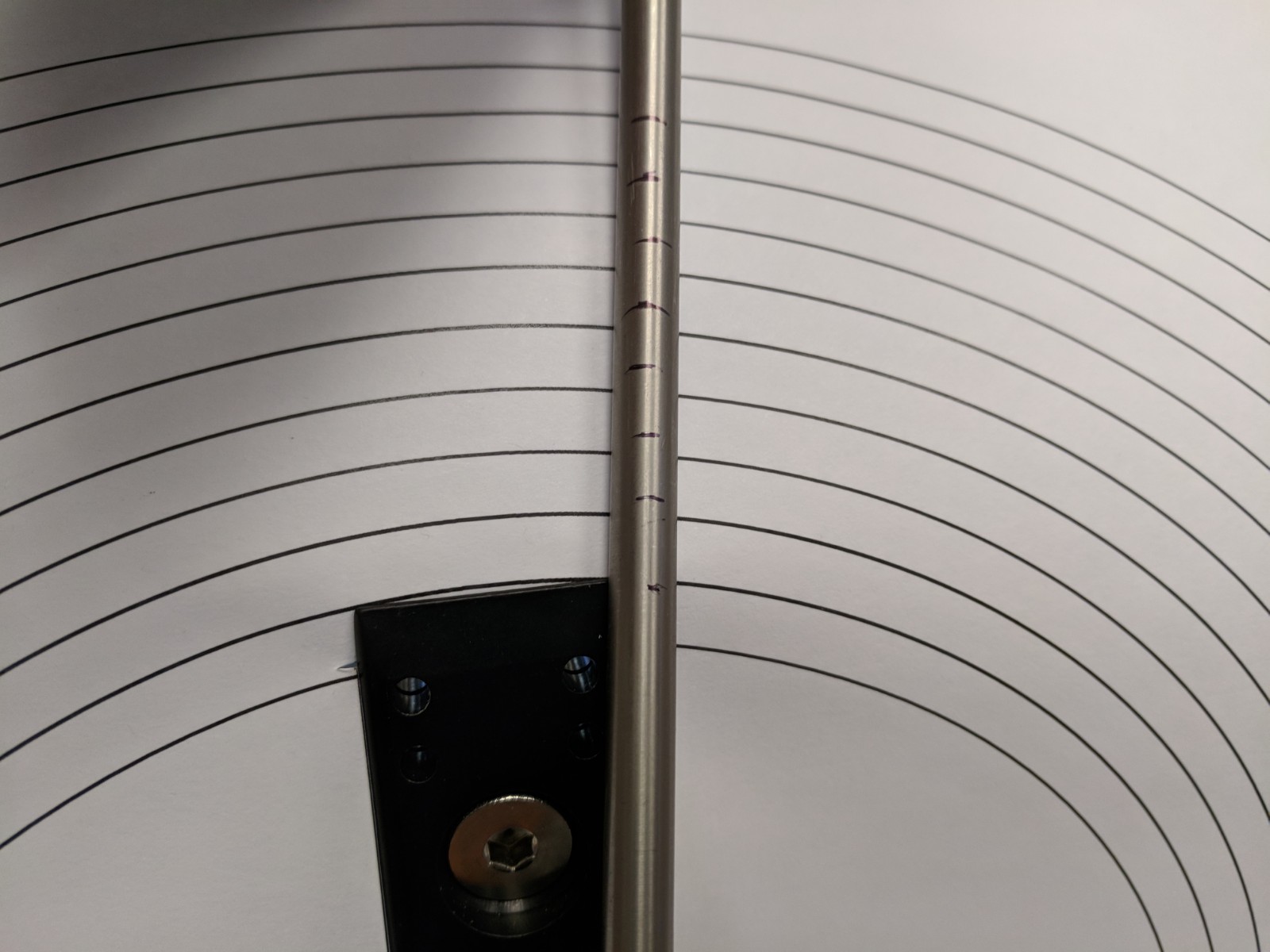
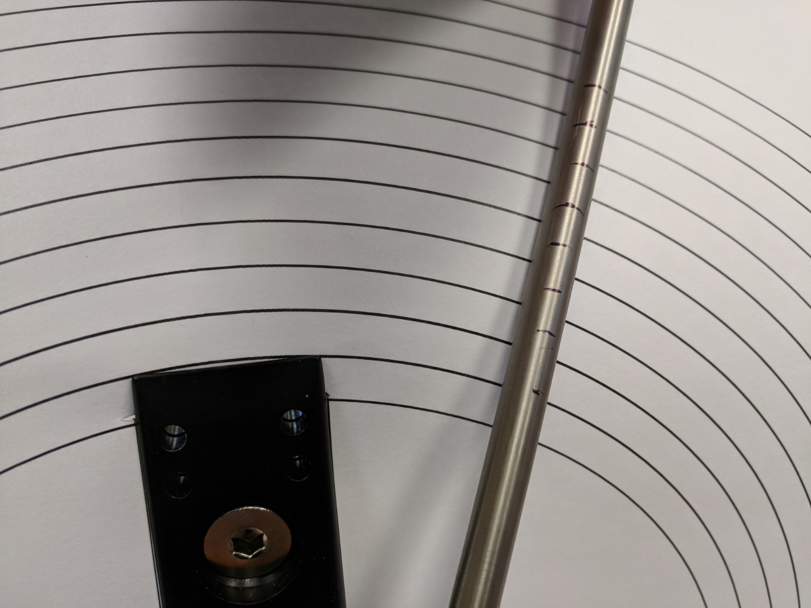
12/22/2017 at 2:09 pm #44088Hi Clay, you must have been testing something different from what I was thinking. What are we looking at here, and more importantly, what conclusion did you reach?
I was just checking out how the marks on the guide rod lined up with the semicircles with a starting diameter of 7″. It doesn’t show well in the photos because the paper I was using was flopping around but the marks on the rods lined up pretty well throughout the rotation. I don’t really know what that means yet other than it looks like there are some fun avenues for exploration with the concept. I’ll try to build a sturdier model to test after the Christmas break and see what comes up. Then I guess I’d try it out on some knives to see what it does to bevel widths.
-Clay
1 user thanked author for this post.
12/22/2017 at 2:22 pm #44089Clay, how come you used 7″ diameter (rather than 7″ radius)?
12/22/2017 at 4:20 pm #44093Clay, how come you used 7″ diameter (rather than 7″ radius)?
I think because the vertical distance from the pivot to the top of the vise is 3.5″.
-Clay
12/22/2017 at 5:00 pm #44096Clay, how come you used 7″ diameter (rather than 7″ radius)?
I think because the vertical distance from the pivot to the top of the vise is 3.5″.
I see the logic in that, but my vise measures about 5.75″ vertical from the pivot point on the angle bar to the top of the vise jaws. But either way, I’m scratching my head wondering why the circles I traced out with the guide rod+sharpie on my first cardboard experiment and then transferred that to the workbench where I used the beam compass which matched up at a 7″ radius for the smallest circle (which doesn’t match to either 3.5 or 5.75″ radius). There must be some 3-dimensional geometry issue at play that I’m not seeing at the moment.
1 user thanked author for this post.
12/22/2017 at 5:15 pm #44098Does it have anything to do with the pivot point is out to the side away from the plane of the arc board. You’re not drawing a flat circle or arc like you did with the beam compass, working down flat where your pivot point was at the center and on the same flat plane. You’re leaning into the cardboard at an angle before you touch it to draw your arcs.
Marc
(MarcH's Rack-Its)1 user thanked author for this post.
- Set the guide rod at some angle
-
AuthorPosts
- You must be logged in to reply to this topic.