Another WE Mod
Recent › Forums › Main Forum › Welcome Mat › Another WE Mod
- This topic has 13 replies, 4 voices, and was last updated 01/28/2016 at 7:31 am by
Bill Kirkley.
-
AuthorPosts
-
01/21/2016 at 2:32 pm #30702
Last year I posted my WE mod. I decided to make a smaller version with two vises.
There are some material changes. I used cold roll for the rails on the origional. I plan on using hot rolled this time around.
The bars that hold the paddle arms are 5/16″ on the WE. On this one I am using 3/8″ only because I had it on hand.
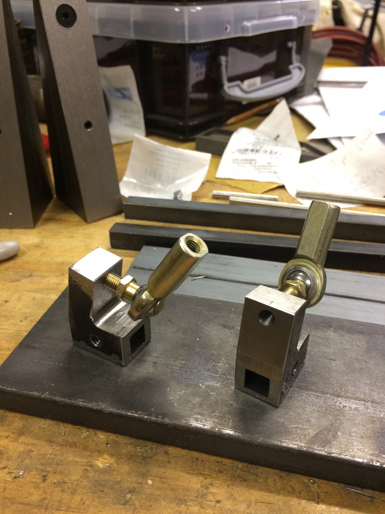
Here are some of the components. You can see the vises in the background.
I will post the finished product when it is complete.
I will post another photo hopefully oriented correctly. I tried to remove the rotated one but could not figure out how. Maybe someone can tell me what to do.
Attachments:
You must be logged in to access attached files.
3 users thanked author for this post.
01/21/2016 at 8:08 pm #30706Looking good Bill, great to see you. Cant wait to see what this one turns out like! 🙂
01/21/2016 at 10:41 pm #30709So Bill… How did you drill the square holes? Do you have a keyseater? Looks like you maybe milled a slot and welded a cap on it.
01/22/2016 at 4:23 am #30714Thanks Curry!
TCMeyer. You figured it out, I milled a slot and spot welded a cap. I filed four recesses and welded at those points. You can see it in the photo.
A broach costs about $130 on MSCDIRECT. I also don’t have a large enough arbor press.
I am thinking about having some kind of finish applied. The finish thickness is a problem as the square holes are only about 3-4 thousands larger than the square rods. Does anyone have any suggestions? I think powder coating is too thick.
01/22/2016 at 8:39 am #30716Looking good, Bill. I wouldn’t apply a finish to it. I think it looks rad the way you have it
Alan
01/22/2016 at 8:44 am #30717You could mask the square bore and the threads (insert full length screws) then powder coat the rest. Or just insert the screws and chrome plate it, square bore and all. You can ask the chrome-plater to limit the chrome thickness to some small number, like 0.001″ or less. There are any of a number of coating options, including black oxide, bluing by your friendly neighborhood gunsmith, high-temp rattle-can paints, etc. Check out the paint options at your local auto parts store.
Josh at Razor Edge Knives on this forum does Ceracoating, which is a form of ceramic coating. I just saw a show on TV where Stag Arms is offering custom Ceracoating on their AR rifles – only $75. You could Ceracoat all of your WE parts.
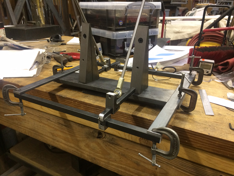
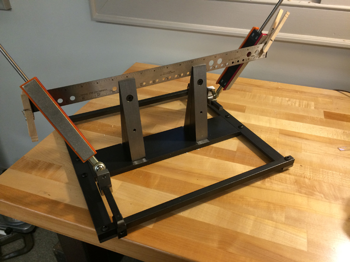
01/25/2016 at 11:12 am #30735It’s getting there. The attached photo shows the rails on the bottom of the cross pieces. I think I will put them on the top instead as the square piece that holds the arm will be too low in this configuration. More to come as I finish it. I used 10 1/2 inch stainless slide arms. Is that what you guys use?
Attachments:
You must be logged in to access attached files.
01/25/2016 at 1:03 pm #30737Each time I found myself with a knife mounted higher and higher, I’d make a longer pair of rods. Right now I’m at 14″ and really, the added length isn’t a significant concern. It’s just a little farther I have to reach to slide on the next stone blocks. How’d I end up at 14″? I had a very small blade with a very low bevel angle. When I mounted it in my Tormek Small Knife Adapter and mounted that in my Low Angle Adapter, I was up in the clouds. To boot, my home-made blocks have bronze bushings with an over-sized bore. This means that if I reach the end of the rod, it slips out of the bushing and the angle changes slightly. If not for that, I could be at 12″ and be happy.
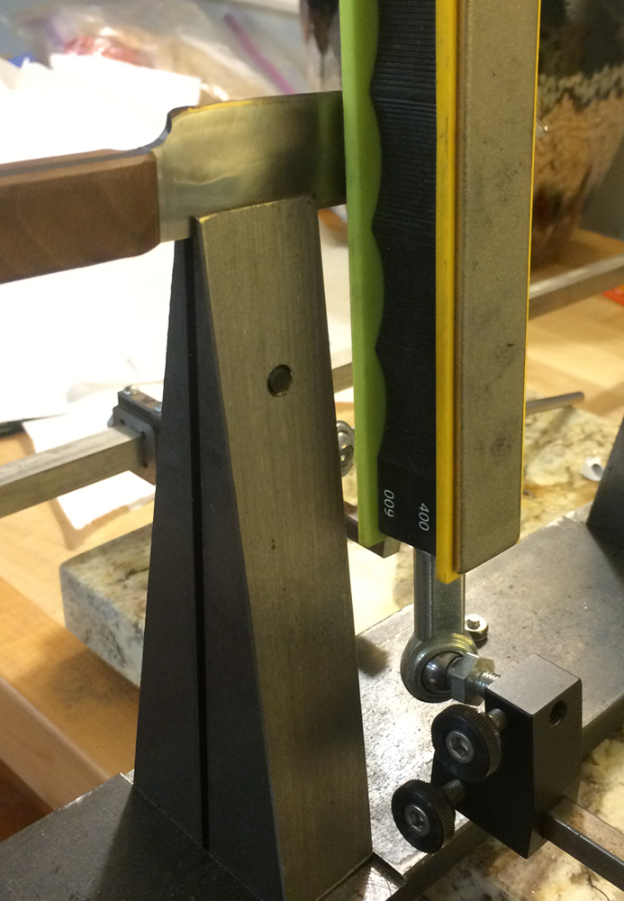
BTW Bill, I think I see in your photo that you have the square angle bar attached to the movable jaw of the left (as seen in the photo) vise. Isn’t that going to be a problem if you jack the movable jaw to accommodate an FFG blade?? The easy fix might be to reverse the vise on the left.
At one point, it occurred to me that the WE vise was configured so that you didn’t use the top inch or so of the stones, except on wider blades. To regain the inch, I cut off part of the rod-end coupling, reducing the amount of thread engagement to only about three turns. Since there is no longitudinal force to speak of, this isn’t a problem. Of course, I cut off the unused threads from the rod as well. End result, longer strokes on narrow blades. Longer strokes mean longer life. No innuendo intended.
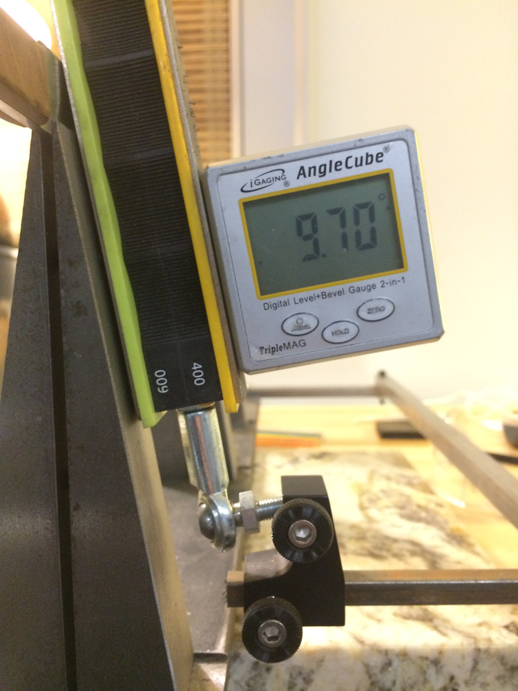
01/25/2016 at 1:31 pm #30738tcmeyer Is the area circled in red the place you are talking about? If so, the square rod is not attached to the vise. The end of the rod is about 1/2 inch away from the vise.
The swivel ball I got only gives me a maximum angle of 32 degrees. I am an novice when it comes to blades but I guess that will do for most blades I sharpen. Another down side is it does not have the hex socket in the end. Does anyone know where to get the ball sockets used in the WE?

Attachments:
You must be logged in to access attached files.
1 user thanked author for this post.
01/25/2016 at 1:39 pm #30740The nice thing about this design is that I no longer need the low angle adapter. I can slide the bar over so it is between the vises and get a pretty low angle.
01/26/2016 at 1:43 am #30750I don’t think I’m understanding how you’re using the two vises, or how moving the degree bar results in a lower angle. If you view the vise/rod from the end, the angle is constant, regardless of the relationship between the relative Y positions of the rod end and the blade, assuming that the blade edge is a straight horizontal line.
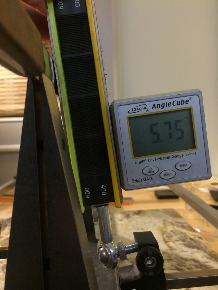
01/26/2016 at 5:16 am #30753By placing the assembly between the vises you can move it closer to the blade which gives you a smaller angle. This only works if the whole blade is off set from the vise. If the blade is clamped in the vise, you would need the low angle attachment. On my new Mod I made the bar longer so it is closer to the vise so I can get a smaller angle.
Attachments:
You must be logged in to access attached files.
01/26/2016 at 5:36 am #30757The two vises allow you to clamp longer blades with greater stability than can be achieved with a single vise. The new mod will clamp about a 16 inch blade. The original one will clamp a blade about 24 inches long, in reality longer than anything I will ever sharpen. When I came up with the design, it wasn’t much trouble adding a third vise, so I did.
01/28/2016 at 7:31 am #30799I finished the WE Mod. I am pleased with how it turned out. I will probably clamp it to the table with a C clamp as opposed to using some type of base. It turns out I can sharpen an 18 inch blade without having to move it in the clamps.
Attachments:
You must be logged in to access attached files.
3 users thanked author for this post.
-
AuthorPosts
- You must be logged in to reply to this topic.