Advanced alignment guide
Recent › Forums › Main Forum › Product Announcements › Advanced alignment guide
- This topic has 189 replies, 22 voices, and was last updated 05/24/2016 at 3:13 am by
 M1rrorEdge.
-
AuthorPosts
-
02/12/2016 at 4:10 pm #31202
Ok, I finished my test.
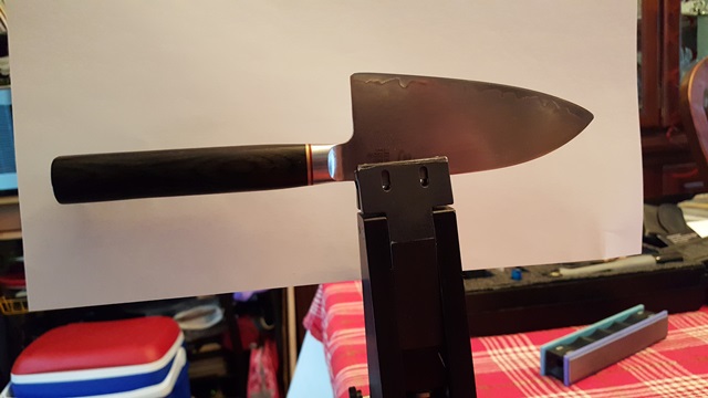
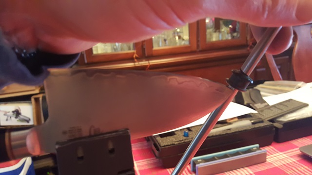
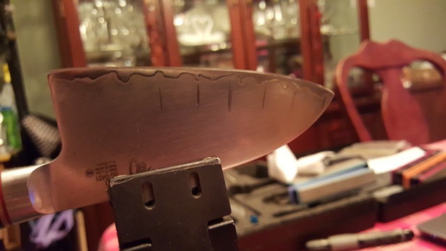
- Setup knife with o-ring as best as I could see visually
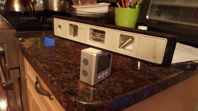
- Put 6 marks on knife for cube measurement with bubble level taped on (Bubble Cube)
- Reground to burr at 13 DPS bar setting (did not bother verifying the Bar with the cube)
- Brought it up thru 600 stone (50 passes each side)
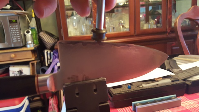
- Measured angle with Bubble Cube at 6 marks (tried as best as I could to “not” bias my reading – by taking multiples, etc; most difficult on the curves but the Bubble Cube helped a lot)
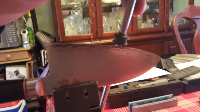
Results (pics below):
PT 1 11.7 deg
Pt 2 11.7 deg
Pt 3 11.6 deg
Pt 4 11.3 deg
Pt 5 10.6 deg
Pt 6 10.6 deg
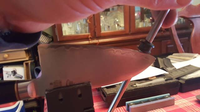
Noticed:
- Slop between rod and stone hole changed readings by ~0.5 deg
- Twist of stone at a point (especially curves) changed readings by ~0.5 deg
- If you carefully sharpen straight up and down with the Bubble Cube fixed to stone (which verifies position) the reading changes very little
- While in step 3 if you move take the stone off the knife and come back to the same spot (which Bubble Cube verifies) you get the same readings
Conclusion:
There are enough error sources at work here between the optimal o-ring setup, sharpening and measuring to account for any variation against the ideal case (perfect truncated cone in Yan’s work) (ie. the curved bevel). In my opinion you cannot verify the ideal case with this setup – we need to remove known error sources. It is also my opinion that it is heading in the right direction and does correlate with Yan. A diamond coated magnetic steel rod with an accurate flat (for Bubble Cube) would be my next choice. Do you happen to have one of those from your prototyping phase ?
Attachments:
You must be logged in to access attached files.
02/12/2016 at 4:13 pm #31207the rest of the pics:
I just noticed that I must have repositioned the knife after the o-ring setup in search of an even better o-ring sweet spot but no position changes were done between sharpening and measuring.
Attachments:
You must be logged in to access attached files.
02/12/2016 at 4:33 pm #31211Anonymous
Inactive- Topics: 14
- Replies: 427
I’m throwing out thoughts here… again I’m not qualified…… you have a knife shown, you put a sharpie on the existing edge… who is to say that , THAT edge is correct.??? wouldn’t it stand to reason if you used the same set up thinking, and the same thoughts, angles and pressure that the path of the stroke would be the same…you would follow the same path each time. but can you actually set up the knife the exact same way, using the same pressures and strokes. insuring all the stackable variables repeat with each knife and with each sharpening, always holding the paddles in the same place. Are you seated in the exact spot so your shoulders and arms bare the same output each time, as you stroke each side of the edge. What effect does 2 lbs of pressure on the paddle have on the left side of the edge, when your right side pressure on that edge is 3 lbs ? If you are using 100 or 200 strokes, it could be more than you think. depending on the grit of the stone being used.
On the other hand , if there is so much variability in the stones, the rods, the pivots stone rotation and their relationship to the actual blade along the stroke, it would seem you are just chasing your tail. BTW, as my screen name might suggest, I am being the devil’s advocate here. with so much variation, how could you repeat the same exact path to the 0.001 inch, if the variability is + – 0.002 inch. for a total of 0.004 inch total variation. All these variable are stackable, making their repeatable precision less than Ideal. Again chasing your tail.
I’ve also noted that there is a deviation in holding the paddle at the bottom of the paddle as oppose to the top of the paddle… where the pressure is more pronounced if you are pushing the paddle at a position which sits above the edge, as oppose to the pressure being directed from the bottom of the paddle.
Again we are not making nuclear triggers here, we are pointing a point on a stick. Much like Homo Erectus. Not disrespect intended here , but the first few days I was here I said to myself… this is way over thought….
This is not Gilligan’s Island, where the doc could make a small nuclear device from a few coconuts, sea shells and some sand.
02/12/2016 at 4:39 pm #31212Inactive- Topics: 14
- Replies: 427
IN my opinion, the only need for the O ring is to set up the radius… trying to keep the pressure constant through out the whole stroke. I try to keep my fingers low on the paddle, through out the stroke, I also try to keep my fingers below the edge, not above it, as I stroke the edge. having the paddle in the same relative position along the edge and through the turn, helps keep the variables low.
02/12/2016 at 4:40 pm #31213I could probably print something like this:
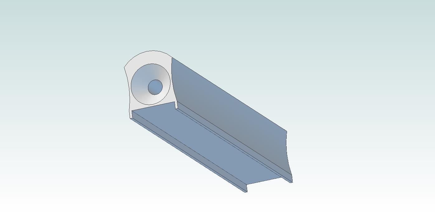
The curved portion is the correct distance from the center of the bore hole to match up with our flat stones, so the geometry should be similar. The channel on the back could fit a piece of bar steel so that the Angle Cube could easily attach. We could use the PSA diamond films over the curved portion to do actual work.
Thoughts?
-Clay
Attachments:
You must be logged in to access attached files.
02/12/2016 at 6:34 pm #31216Interesting, if the radius of the curve is concentric with the rod/hole we might be able to maximize the vector orthogonally to the rod. In other words, the stone point contact to the knife edge will always be perpendicular to the rod for flats and curves. I’m not sure though WDYT. Also, a machinist among us should be able to help with getting a fit of the rod to the hole which would eliminate any slop (at least for testing purposes).
Hey ET, can you work on that part (millionths to you, arc seconds to me) ? No offense intended. We also need an error budget analysis.
Doing it with just the rod might help concept verification but won’t help for actual usage.
BTW, what do you mean “print” this ? Do you have a 3-d printer ?
02/13/2016 at 6:23 am #31226That’s useful practical information, Clay! Can you give us a photograph of how exactly you got the angle cube plumb? And I’m also curious which loupe you used and how you made a photograph through it (or was it a USB loupe?)
Regarding the alignment guide, I was thinking it would be nice if it used standardized distances between the lines. Say centimeters or – for Americans – parts of inches.
I have to ponder your results from the posts at 1:15 pm and 1:25 pm. But the problem with the O-ring method as well as the calculations I made in my blog post on this subject is that it doesn’t take the “planes” into account. By that I mean it only partially takes the rotation of the stone into account. Anthony’s method does.
I’m reading this subject sequentially – you guys did a lot of work yesterday – and now see more people brought up the axial stone rotation. Redhead, you clearly showed there are multiple sources that make practice deviate from the optimal theoretical situation. That’s good to know.
Molecule Polishing: my blog about sharpening with the Wicked Edge
02/13/2016 at 6:30 am #31227I could probably print something like this:
 The curved portion is the correct distance from the center of the bore hole to match up with our flat stones, so the geometry should be similar. The channel on the back could fit a piece of bar steel so that the Angle Cube could easily attach. We could use the PSA diamond films over the curved portion to do actual work. Thoughts?
 That would definitely take some variability away. But not all. And how do you make sure the rotation of the stone doesn’t influence the angle reading (that’s similar to a question I also asked in the O-ring topic).
Molecule Polishing: my blog about sharpening with the Wicked Edge
02/13/2016 at 10:16 am #31232Mark: I think that the purpose of the radial face is to eliminate rocking as a variable. So long as the radius of the stone is constant, the angle will be constant, regardless of stone rotation. Or maybe I’m not understanding your question.
Clay: Can you make a prototype on a 3-D printer? ABS ought to be hard enough to back up film abrasive, and cheap enough to have a limited life (inexpensive replacement).
Maybe the steel plate for the AngleCube attachment needn’t be full length. Use the lower half to add an area for finger placement and protection?
02/13/2016 at 11:50 am #31234You can put a bubble on the top of the angle cube or a second angle cube at 90 deg
02/13/2016 at 12:20 pm #31235Does anyone know how to get in touch with Anthony Yan ? I think he has the Matlab version of the chefs knife. I left him a message via WEPS messaging but he doesn’t seem very active here.
02/13/2016 at 2:27 pm #31239Tom 2 (Readheads). I’ve worked with Anthony and his email address is in your email.
Molecule Polishing: my blog about sharpening with the Wicked Edge
02/15/2016 at 12:15 pm #31278Interesting, if the radius of the curve is concentric with the rod/hole we might be able to maximize the vector orthogonally to the rod. In other words, the stone point contact to the knife edge will always be perpendicular to the rod for flats and curves. I’m not sure though WDYT. Also, a machinist among us should be able to help with getting a fit of the rod to the hole which would eliminate any slop (at least for testing purposes). Hey ET, can you work on that part (millionths to you, arc seconds to me) ? No offense intended. We also need an error budget analysis. Doing it with just the rod might help concept verification but won’t help for actual usage. BTW, what do you mean “print” this ? Do you have a 3-d printer ?
I do have a 3d printer.
-Clay
02/15/2016 at 12:18 pm #31279That’s useful practical information, Clay! Can you give us a photograph of how exactly you got the angle cube plumb? And I’m also curious which loupe you used and how you made a photograph through it (or was it a USB loupe?) Regarding the alignment guide, I was thinking it would be nice if it used standardized distances between the lines. Say centimeters or – for Americans – parts of inches. I have to ponder your results from the posts at 1:15 pm and 1:25 pm. But the problem with the O-ring method as well as the calculations I made in my blog post on this subject is that it doesn’t take the “planes” into account. By that I mean it only partially takes the rotation of the stone into account. Anthony’s method does. I’m reading this subject sequentially – you guys did a lot of work yesterday – and now see more people brought up the axial stone rotation. Redhead, you clearly showed there are multiple sources that make practice deviate from the optimal theoretical situation. That’s good to know.
I picked up a really nice loupe from iGaging that has a big objective lens and clear graticule for measuring. I’m thinking of carrying them on the website. They’re not cheap but they’re really nice to work with, especially because you can get good photos through them.
-Clay
02/16/2016 at 10:55 am #31315In studying the stone as it rotates at the tip, I’ve made a couple observations – it’s difficult to get a reading from the cube because, as you say, only part of the stone is touching the blade so it wants to rock. If you push with your thumb so that the trailing edge of the stone is contacting the blade, the cube reads a higher angle and if you press the leading edge of the stone into the blade, the cube reads a lower angle. What you say with concave curves is also true, only the sides of the stone contact the blade. We do have some curved stones. I’ll play around with measuring the angles using those.
I missed this before, (and this may be dumb), but what if you used a tanto blade to take measurements? Not curved I know, but it gives a flat area at an angle to measure from?
1 user thanked author for this post.
-
AuthorPosts
- You must be logged in to reply to this topic.